Co-Location of a Heat Source Cooling Subsystem and Aquaculture

a heat source cooling and subsystem technology, applied in the field of aquaculture, can solve the problems of large heat produced by electrical components within data centers for these functions, and the operation of electrical components and cooling systems within data centers often requires a large amount of energy, so as to achieve fewer carbon emissions, less energy, and less carbon emissions

Active Publication Date: 2016-01-14
DEEPWATER DESAL
View PDF4 Cites 14 Cited by
  • Summary
  • Abstract
  • Description
  • Claims
  • Application Information

AI Technical Summary

Benefits of technology

[0008]Systems of the present disclosure, in various instances include a data center having a water cooling subsystem configured to receive cool water and output warm water and an aquaculture center co-located with the data center and comprising a water temperature control subsystem configured to receive the output warm water. In some embodiments, the cool water is received from an ocean or sea.
[0009]Certain embodiments of the systems having a water cooling subsystem include a water intake. The water intake may, in some aspects, be positioned at a depth of 15 m or more, such as 20 m or more, 25 m or more, 30 m or more, 35 m or more, etc. in a water source. In particular variations, the water intake is positioned below the photic zone in a water source.
[0010]In select versions, the systems include a water discharge configured for discharging water from the aquaculture center. The water discharge is, in particular embodiments, positioned at a depth of 15 m or more in a body of water (e.g., an ocean or sea), such as 20 m or more, 25 m or more, 30 m or more, 35 m or more, etc., in a water source. In some embodiments, the body of water in which the water discharge is positioned is the same ocean or sea in which the water intake of a system is positioned.
[0011]The power usage effectiveness (PUE) of the data center of the disclosed systems, in some aspects, is 2 or less. In some aspects, the PUE of the data center of the disclosed systems is between 1 and 1.3. In some instances, the data center and aquaculture center of the disclosed systems are configured to produce fewer carbon emissions as compared to the same data center

Problems solved by technology

The operation of electrical components within data centers for these functions produces a large amount of heat.
Operation of electrical components and cooling systems wi

Method used


Image

  • Co-Location of a Heat Source Cooling Subsystem and Aquaculture
  • Co-Location of a Heat Source Cooling Subsystem and Aquaculture
  • Co-Location of a Heat Source Cooling Subsystem and Aquaculture

Examples


Embodiment Construction

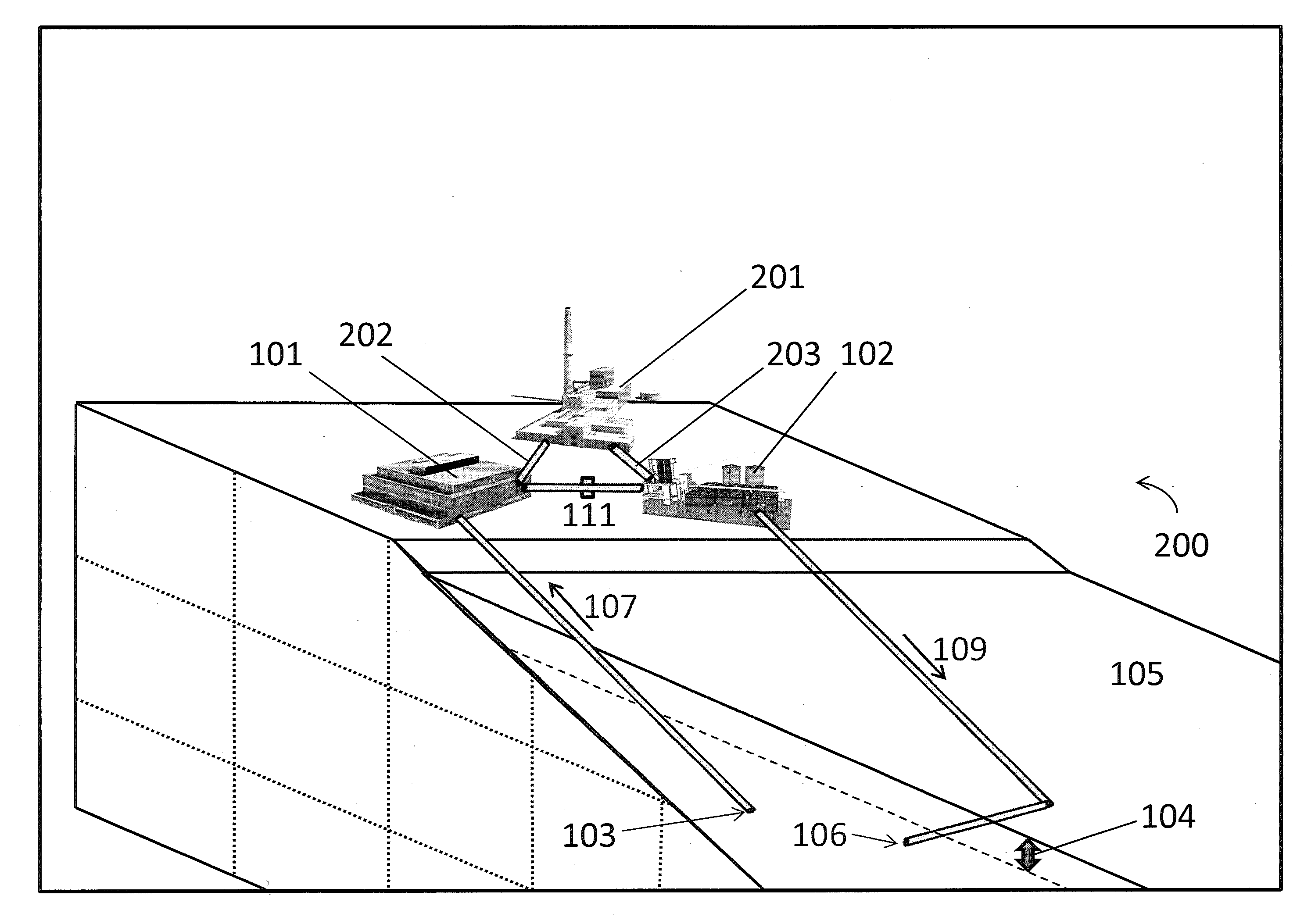
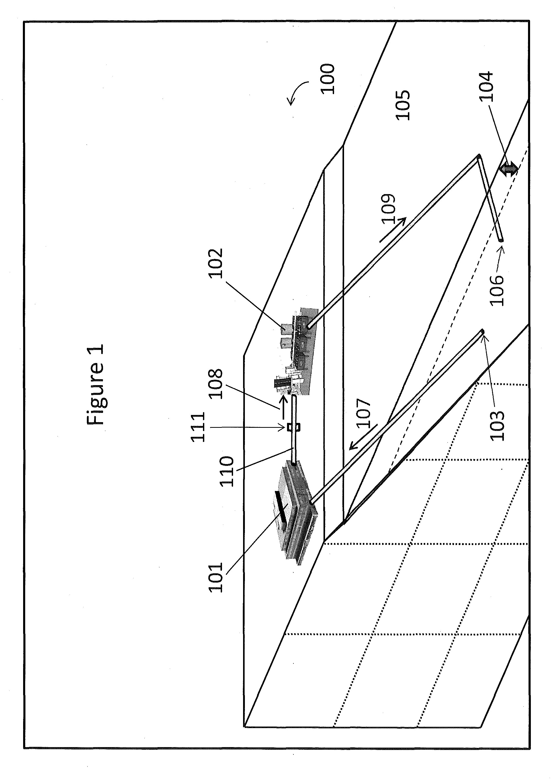
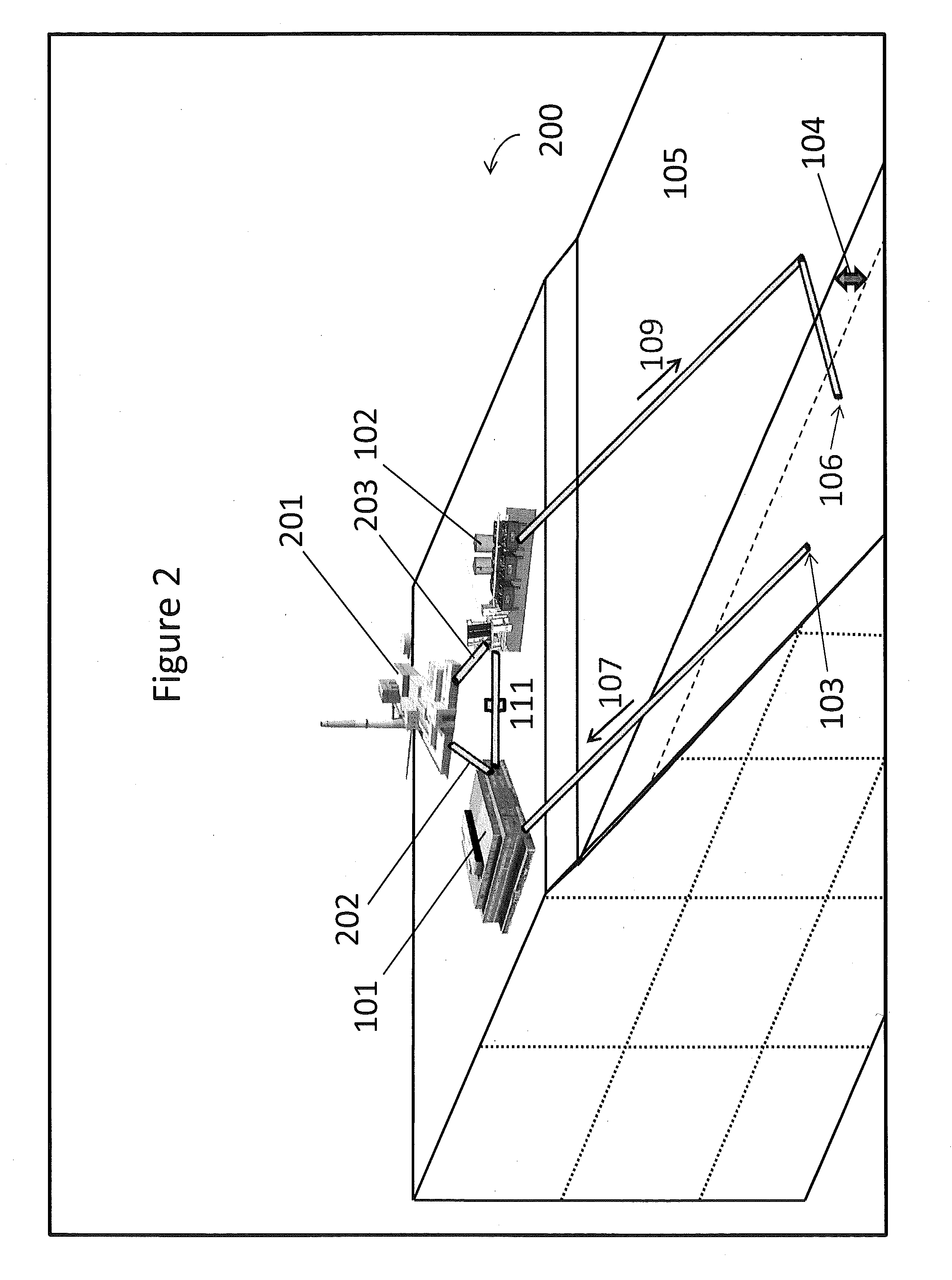
[0024]The present disclosure provides systems for heat source, e.g., data center, cooling and aquaculture. In certain aspects, the systems include a heat source, e.g., data center, having a water cooling subsystem configured to receive cool water and output warm water and an aquaculture center co-located with the heat source, e.g., data center, and configured to receive the warm water. Aspects of the invention also include methods for cooling a heat source, e.g., data center, using a water cooling subsystem and cultivating aquatic organisms with an aquaculture center that is co-located with the heat source, e.g., data center.

[0025]Before the present invention is described in greater detail, it is to be understood that this invention is not limited to particular embodiments described, as such may, of course, vary. It is also to be understood that the terminology used herein is for the purpose of describing particular embodiments only, and is not intended to be limiting, since the sco...


PUM


Abstract

The present disclosure provides systems for heat source, e.g., data center, cooling and aquaculture. In certain aspects, the systems include a heat source, e.g., data center, having a water cooling subsystem configured to receive cool water and output warm water and an aquaculture center co-located with the heat source, e.g., data center, and configured to receive the warm water. Aspects of the invention also include methods for cooling a heat source, e.g., data center, using a water cooling subsystem and cultivating aquatic organisms with an aquaculture center that is co-located with the heat source, e.g., data center.

Description

CROSS-REFERENCE TO RELATED APPLICATIONS[0001]Pursuant to 35 U.S.C. §119 (e), this application claims priority to the filing date of the U.S. Provisional Patent Application Ser. No. 61 / 800,481 filed Mar. 15, 2013; the disclosure of which application is herein incorporated by reference.INTRODUCTION[0002]In recent years, internet traffic in the United States has risen significantly. It is estimated that in the United States, internet traffic increased from 40,000-70,000 terabytes / month in 2001 to 3,400,000-4,100,000 terabytes / month in 2011. To support the steep growth in internet traffic, a large amount of computer-related infrastructure has been developed and implemented. One type of infrastructure that has been increasingly utilized is data centers.[0003]Data centers are facilities that house computer systems and associated components for operation therein. Data centers may include computers, data storage devices, servers, telecommunications systems or other related equipment and may...

Claims


Application Information

Patent Timeline
IPC IPC(8): A01K63/06A01K63/00
CPCA01K63/003A01K63/065H05K7/2079Y02E10/30A01K61/00Y02A40/81A01K63/00A01K61/54A01K61/10
Inventor CONSTANTZ, BRENT, R.
Owner DEEPWATER DESAL
Why Eureka
Try Eureka