Controlled speed friction stir tool probe bodies having non-linear, continuous, monotonically-decreasing curved axial profiles and integrated surface features

a technology of friction stir and probe body, which is applied in the direction of manufacturing tools, soldering devices, auxillary welding devices, etc., can solve the problems of reducing the amplitude of side-to-side oscillation of the tool, and affecting the amplitude of side-to-side oscillation

Inactive Publication Date: 2016-01-14
BURFORD DWIGHT A +1
View PDF2 Cites 23 Cited by
  • Summary
  • Abstract
  • Description
  • Claims
  • Application Information

AI Technical Summary

Benefits of technology

[0017]The above and other needs are met by aspects of the present disclosure which, in one aspect, provides a friction stir processing tool comprising a material flow path defined by a distal end of an outer surface of a probe body. The distal end of the probe body is adapted to engage a workpiece material to perform a friction stir process, and the probe body is rotatable about an axis ther

Problems solved by technology

Yet, because of the localized nature of the process, friction stir processes induce steep thermal gradients in the workpiece(s) that are significantly greater than those typically produced in bulk-forming operations.
. . chaotic oscillations in FSW tend to be associated with the formation of volumetric defects (voids) within the joint, resulting from the lack of consistency in the reconsolidation of material along the joint line.” The oscillating motion or pattern of the advancing, rotating tool is affected by the amount of energy that is transferred into the workpiece material immediately around the rotating-traversing tool.
When the level of energy or heat input is increased, the extent of material softening ahead of the tool correspondingly increases, which in turn tends to dampen the amplitude of side-to-side oscillations of the tool.
As a result of this periodic nature of friction stir processes, the tool, especially the probe, experiences rotating, bending fatigue at elevated temperatures.
Strong oscillating traverse forces acting on the traversing tool, incl

Method used


Image

  • Controlled speed friction stir tool probe bodies having non-linear, continuous, monotonically-decreasing curved axial profiles and integrated surface features
  • Controlled speed friction stir tool probe bodies having non-linear, continuous, monotonically-decreasing curved axial profiles and integrated surface features
  • Controlled speed friction stir tool probe bodies having non-linear, continuous, monotonically-decreasing curved axial profiles and integrated surface features

Examples


Embodiment Construction

[0049]The present disclosure will now be described more fully hereinafter with reference to exemplary aspects thereof. These exemplary aspects are described so that this disclosure will be thorough and complete, and will fully convey the scope of the disclosure to those skilled in the art. Indeed, the disclosure may be expressed in many different forms and should not be construed as limited to the aspects set forth herein; rather, these aspects are provided so that this disclosure will satisfy applicable legal requirements. As used in the specification, and in the appended claims, the singular forms “a”, “an”, “the”, include plural referents unless the context clearly dictates otherwise.

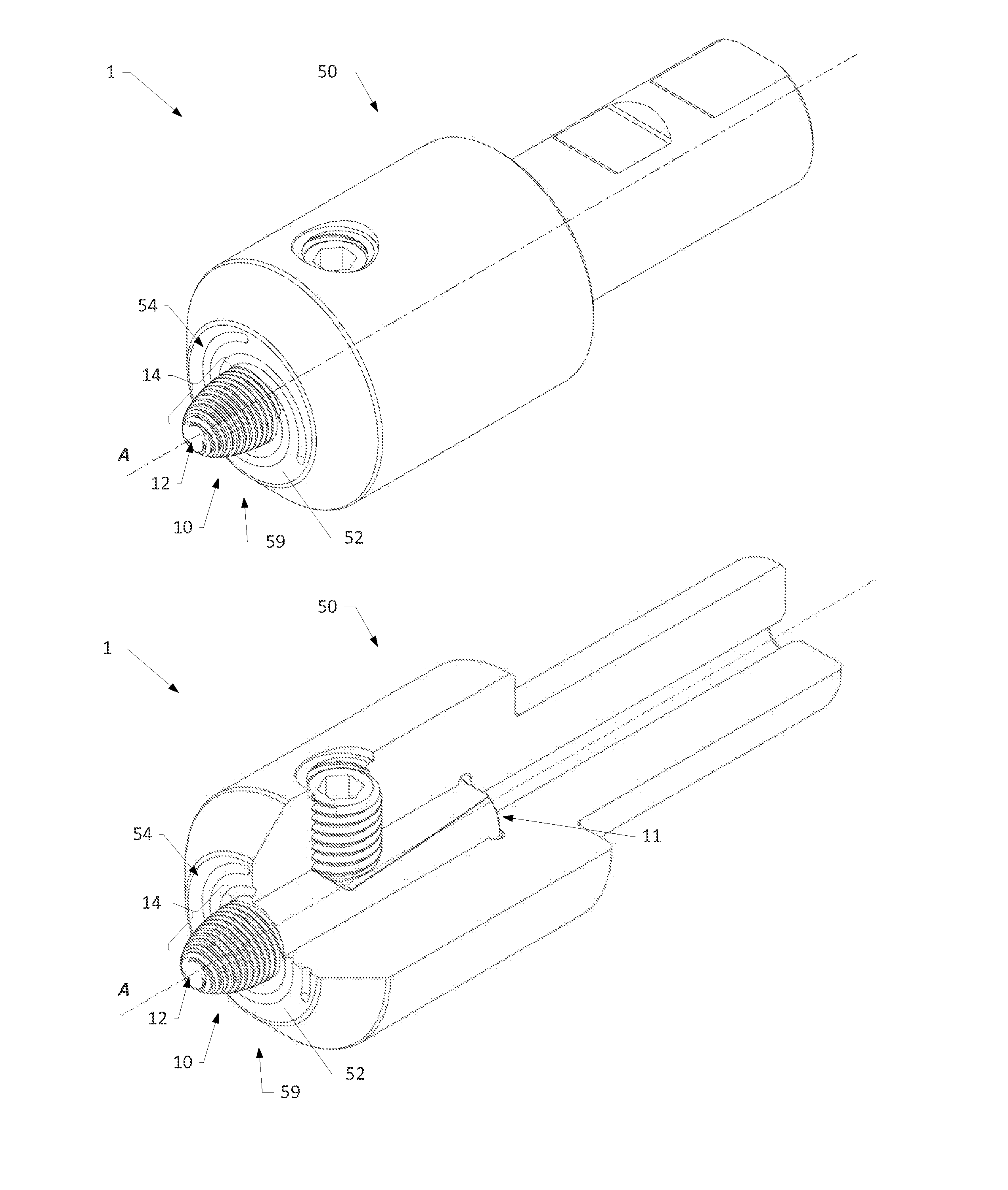
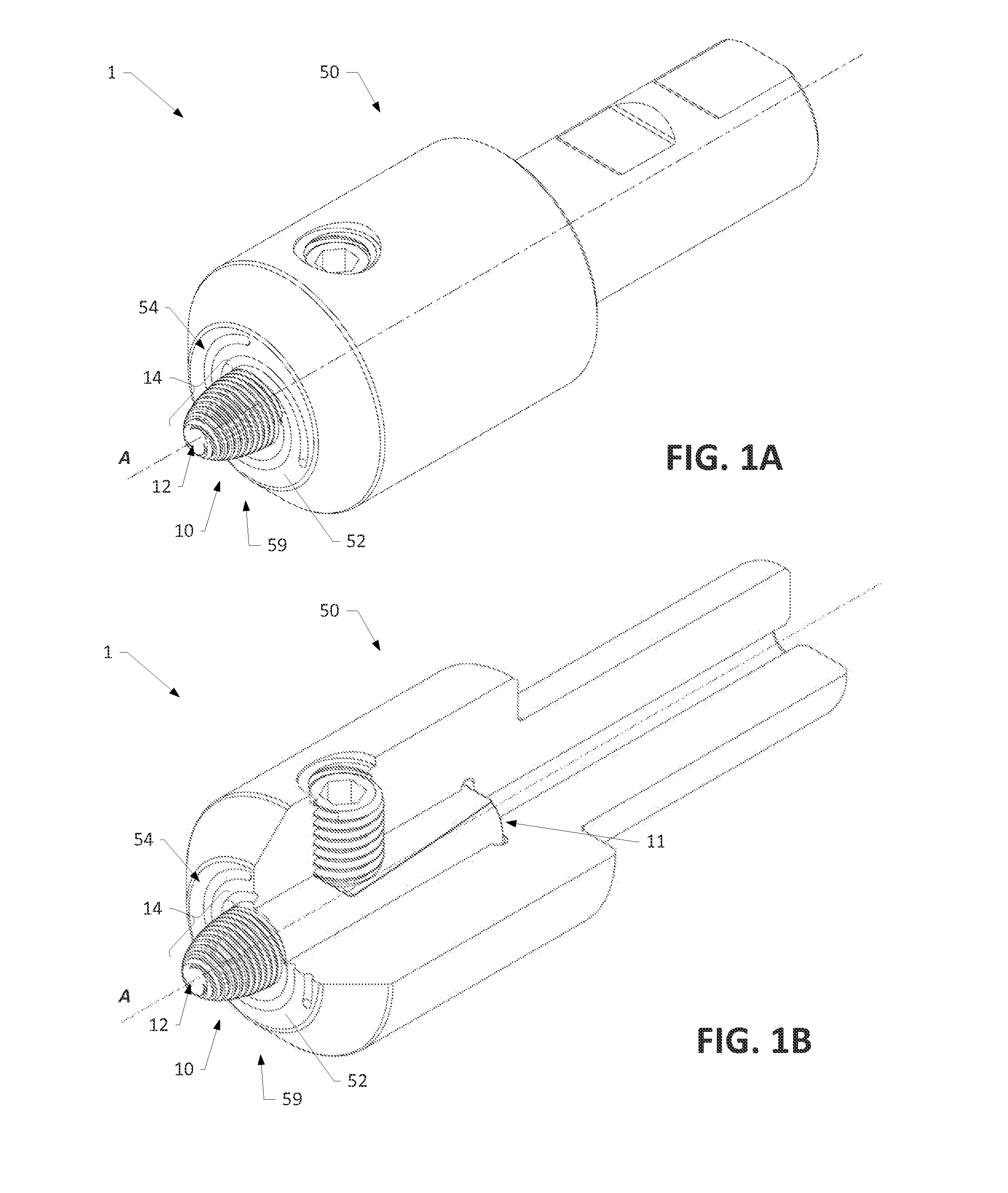
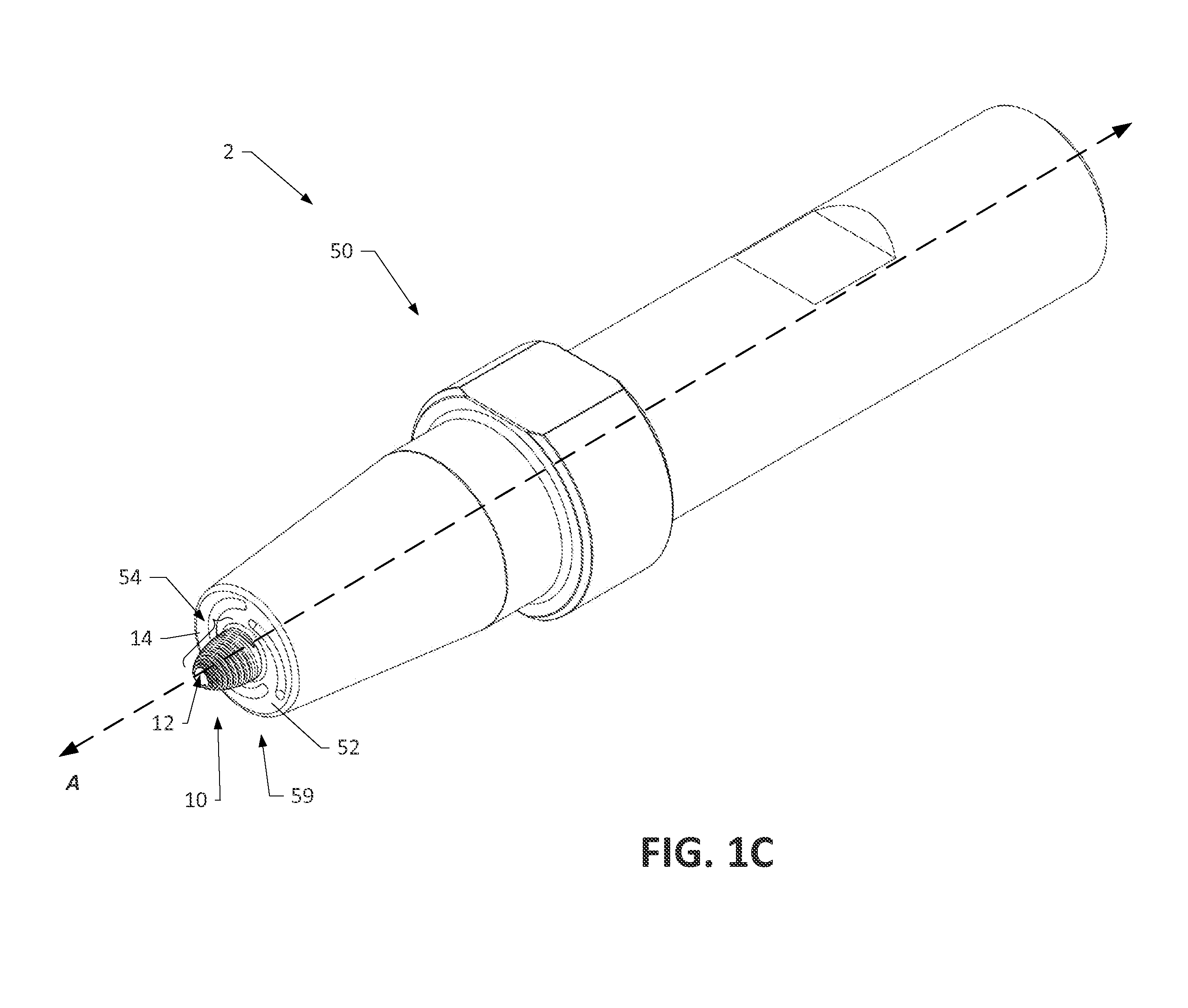
[0050]Various aspects of the present disclosure generally relate to a friction stir processing tool configured to be used in friction stir welding (FSW), friction stir spot welding (FSSW), and / or friction stir processing (FSP) of malleable materials, such as non-ferrous metals and related alloys. FIG...


PUM

PropertyMeasurementUnit
Flow rateaaaaaaaaaa
Speedaaaaaaaaaa
Surfaceaaaaaaaaaa

Abstract

A friction stir processing tool and method for manufacturing the same are provided. The tool includes a non-consumable, interchangeable friction stir probe body. The tool includes a material flow path defined by an outer surface of a probe body, which has a non-linear, continuous, monotonically-decreasing axial profile. The probe body is adapted to engage a workpiece material to perform a friction stir process by rotating about an axis thereof thereby directing a weld material toward a distal end of the probe body along the flow path. The flow path varies in pitch as the lateral cross-sectional dimension of the probe body decreases toward the distal end thereby causing the weld material to maintain a controlled speed as it travels along the flow path. Geometric surface features such as threads, helical grooves, ridges, flutes, and/or flats, integrated with the probe body may define the flow path.

Description

CROSS-REFERENCE TO RELATED APPLICATIONS[0001]The present application claims priority to U.S. Provisional Patent Application No. 62 / 023,485, filed Jul. 11, 2014, which is incorporated herein by reference in its entirety.BACKGROUND[0002]1. Field of the Disclosure[0003]Aspects of the present disclosure generally relate to friction stir processing tools adapted to engage a workpiece in a friction stir processing technique, such as friction stir welding (FSW), friction stir spot welding (FSSW), and / or friction stir processing (FSP), and in particular, to friction stir processing tools that provide for a controlled speed of weld material along a material flow path on and along the probe surface.[0004]2. Description of Related Art[0005]Tools and processes for producing continuous butt joints by friction stir welding between two or more workpieces made of “metals, alloys or compound materials such as MMC, or suitable plastic materials such as thermo-plastics” is disclosed by Intl. Pub. No. ...

Claims


Application Information

Patent Timeline
IPC IPC(8): B23K20/12
CPCB23K20/1245B23K20/1255
Inventor BURFORD, DWIGHT, A.
Owner BURFORD DWIGHT A
Why Eureka
Try Eureka