Solid state joining using additive friction stir processing

a technology of additive friction stir and solid-state joining, which is applied in the direction of manufacturing tools, non-electric welding apparatuses, welding/soldering/cutting articles, etc., can solve the problems of limitless dimensions of stiffening ribs, and achieve high melting point, reduce galvanic corrosion, and reduce tool wear and breakage

Active Publication Date: 2016-12-06
MELD MFG CORP
View PDF301 Cites 19 Cited by
  • Summary
  • Abstract
  • Description
  • Claims
  • Application Information

AI Technical Summary

Benefits of technology

[0009]Advantages of the invention include reduced tool wear and breakage resulting from the use of filler metal for penetrating and forming the base metal instead of the tool penetrating the workpiece(s). In addition, high melting point materials, alloys and particle / short fiber reinforced composite can be welded with already available tool materials. Further, the solid state nature of the process allows for using similar filler metal as base metal, which will reduce galvanic corrosion. Another potential benefit is achieving a weld quality that is insensitive to tool wear (especially where axial pressure is maintained). As a result of these advantages, the present invention is a viable, economic, and efficient alternative to conventional welding processes that can be used to weld or join a variety of high temperature materials with or without the help of external heating and assistance from resistance heating, gas torch heating, arc heating, ultrasonic vibrations, microwave heating and induction hearting and so on.

Problems solved by technology

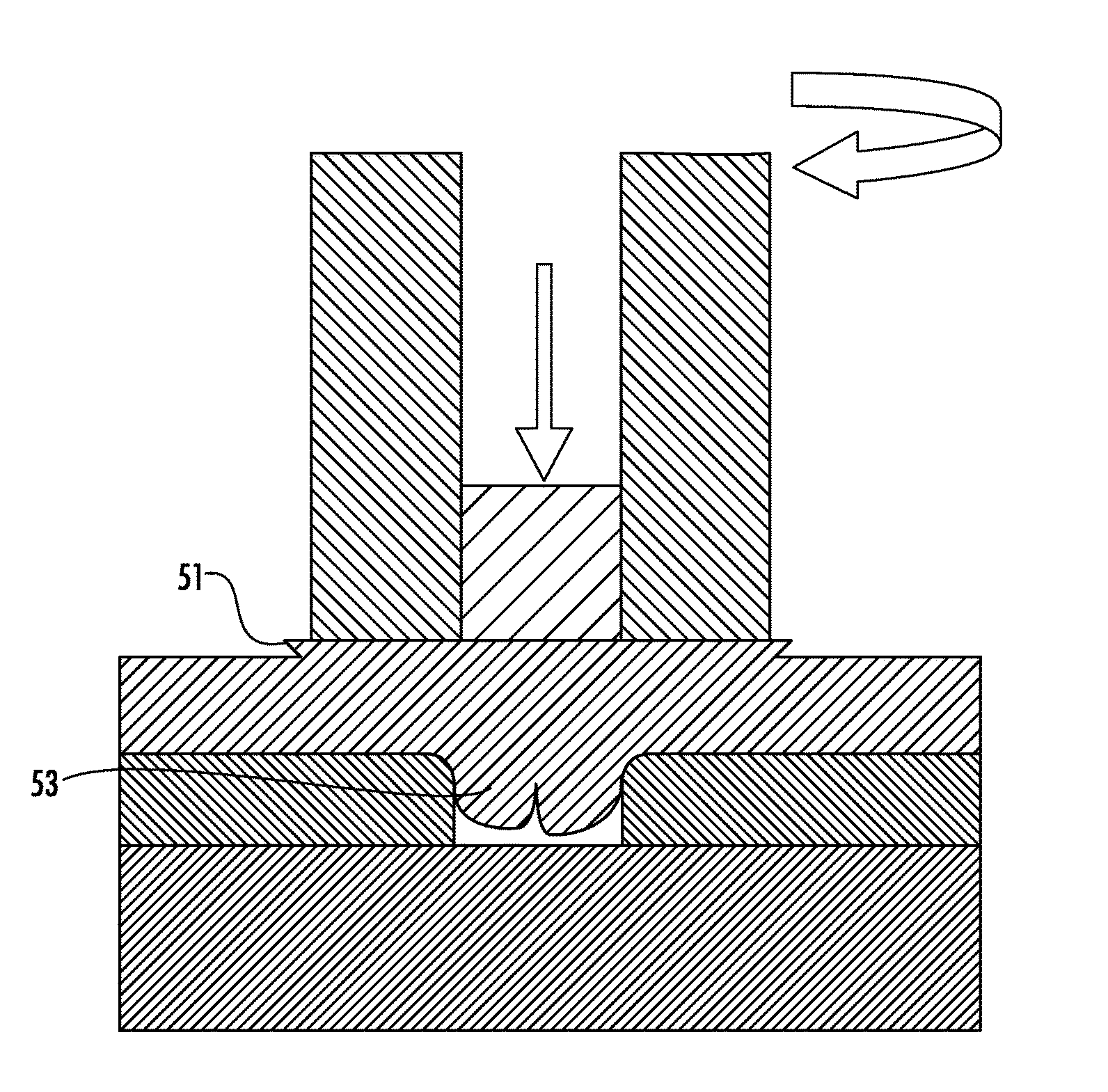
Due to the additive nature of the additive friction stir technology, the dimensions of the stiffening ribs can be limitless since the dimensions are only limited by the amount of filler material that is delivered during the process, which in some embodiments can be continuous and limitless.

Method used


Image

  • Solid state joining using additive friction stir processing
  • Solid state joining using additive friction stir processing
  • Solid state joining using additive friction stir processing

Examples


example

[0084]Diagrams showing substrates joined using an embodiment of the additive friction stir methods of the invention are provided in FIGS. 8A-B, and 9. In particular, two HY-80 steel substrates were welded together with a filler material comprising HY-80. HY-80 steel is an alloy comprising several metals. Typically, HY-80 steel comprises on a percent by weight basis about 93-97% Iron (Fe), about 2-4% Nickel (Ni), about 1-2% Chromium (Cr), ≦ about 0.25% Copper (Cu), about 0.2-0.6% Molybdenum (Mo), about 0.15-0.35% Silicon (Si), about 0.12-0.18 Carbon (C), about 0.1-0.4% Manganese (Mn), ≦ about 0.025% Phosphorous (P), ≦about 0.025% Sulfur (S), ≦ about 0.020% Titanium (Ti), and ≦ about 0.030% Vanadium (V). The density of HY-80 steel is typically about 7.87 g / cc and the melting point is around 1424° C. FIG. 8A shows one side of the substrates joined and FIG. 8B shows the other side of the substrates facing in an opposing direction. As illustrated, the deposited filler material can be see...


PUM

PropertyMeasurementUnit
lengthaaaaaaaaaa
melting pointaaaaaaaaaa
densityaaaaaaaaaa

Abstract

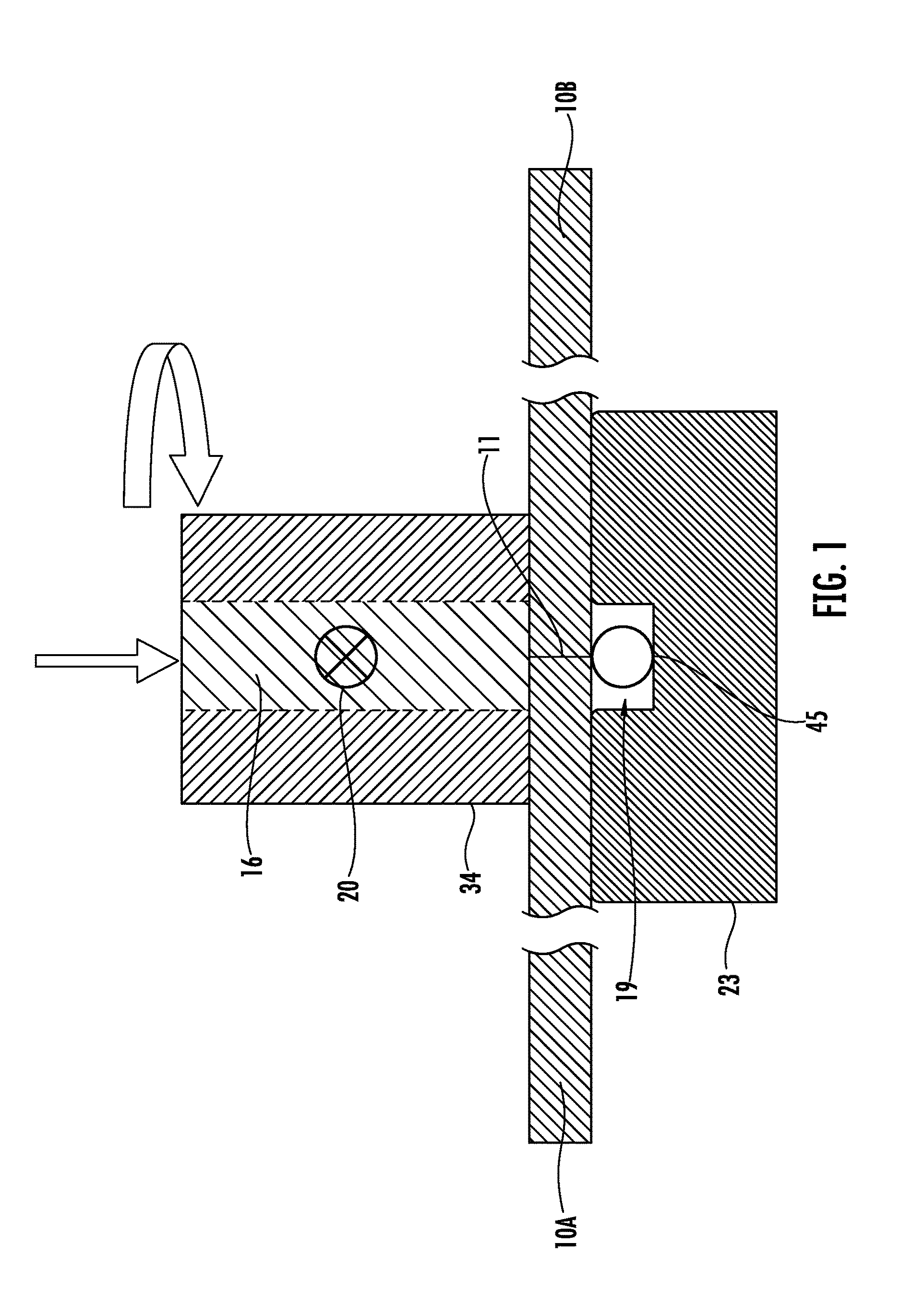
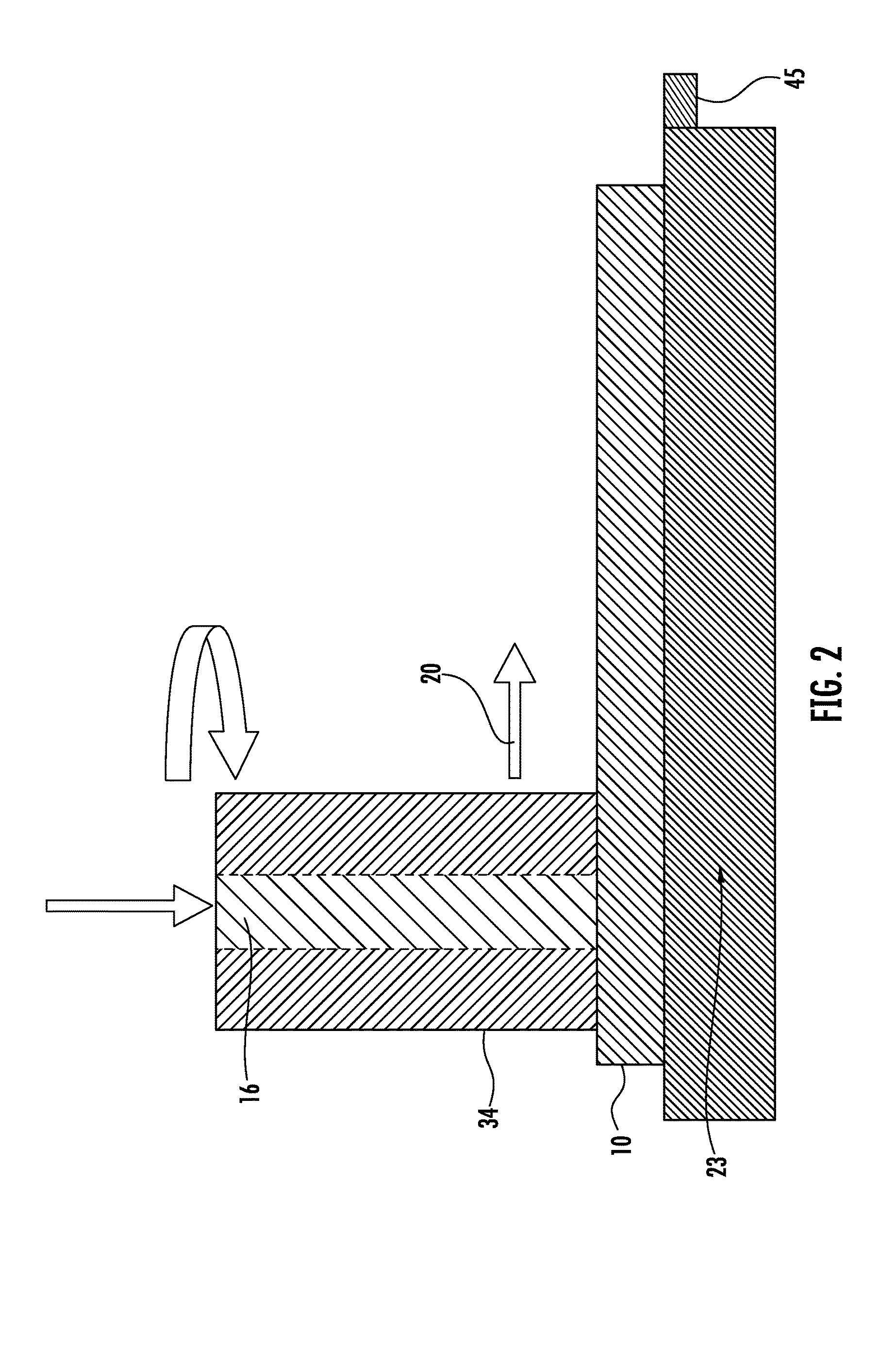
Additive friction stir methods for joining materials are provided. The methods comprise providing first and second substrates to be joined; providing a forming plate comprising one or more forming cavities; placing the first and second substrates in communication with the forming plate; placing the first and second substrates in communication with each other; rotating and translating an additive friction-stir tool relative to the substrates; feeding a filler material through the additive friction-stir tool; deforming the filler material and the first and second substrates; and extruding one or more of the filler material and the first and second substrates into one or more of the forming cavities of the forming plate. Interaction of the friction-stir tool with the substrates generates plastic deformation at the joint to weld the substrates at the joint. The methods include introduction of reinforcing material at the joint through addition of the filler material.

Description

CROSS-REFERENCE TO RELATED APPLICATIONS[0001]The present application is a Continuation-in-Part (CIP) of U.S. patent application Ser. No. 14 / 573,430 filed Dec. 17, 2014, the disclosure of which is incorporated herein by reference in its entirety.BACKGROUND OF THE INVENTION[0002]1. Field of the Invention[0003]The present invention is in the fields of solid state manufacturing, including material joining or welding and additive manufacturing. In particular, the invention is in the field of additive friction-stir joining of materials.[0004]2. Description of Related Art[0005]Friction-stir processing provides for the solid state joining of pieces of metal at a joint region through the generation of frictional heat at the joint and opposed portions of the metal pieces by cyclical movements of a tool piece that is harder than the metal pieces. An example of this is provided by International Application Publication No. PCT / GB1992 / 002203. Frictional heat produced between the substrate and the...

Claims


Application Information

Patent Timeline
Patent Type & Authority Patents(United States)
IPC IPC(8): B23K20/12B23K20/227B23K20/233B33Y10/00
CPCB23K20/1215B23K20/1205B23K20/128B23K20/129B23K20/1245B23K20/1295B23K20/2275B23K20/2333B23K20/2336B23K2203/02B23K2203/04B23K2203/08B23K2203/10B23K2203/12B23K2203/14B23K2203/15B23K2203/18B23K2203/20B23K2203/22B23K2203/24B23K2203/26B33Y10/00B23K2103/05B23K2103/02B23K2103/04B23K2103/08B23K2103/10B23K2103/12B23K2103/14B23K2103/15B23K2103/18B23K2103/20B23K2103/24B23K2103/26B23K2103/22B23K20/1255
Inventor KANDASAMY, KUMAR
Owner MELD MFG CORP
Why Eureka
Try Eureka