Stir forming apparatus and method

a technology of forming apparatus and forming method, which is applied in the direction of soldering apparatus, manufacturing tools,auxillary welding devices, etc., can solve the problems of increasing the manufacturing time and cost of structural members, affecting and cracking or weakened portions that may result from excessive forming, etc., to achieve the effect of improving the material properties of workpieces

Active Publication Date: 2008-11-11
THE BOEING CO
View PDF36 Cites 20 Cited by
  • Summary
  • Abstract
  • Description
  • Claims
  • Application Information

AI Technical Summary

Benefits of technology

[0007]The present invention provides an apparatus and method for forming a workpiece to a desired, non-planar configuration with at least one friction stir forming tool. The forming tool plasticizes a portion of the workpiece and urges the workpiece to the desired configuration, thereby refining the grain structure of the workpiece. Thus, the workpiece can be formed to any desired configuration, including complex shapes. In addition, the material properties of the workpiece can be improved.

Problems solved by technology

However, depending on the particular material of the preform, cracks or weakened portions may result from excessive forming, e.g., the formation of sharp angles or other significant deformations.
These additional operations add to the manufacturing time and cost of the structural members.
However, this process is also time-consuming and adds to the cost of the structural member.

Method used


Image

  • Stir forming apparatus and method
  • Stir forming apparatus and method
  • Stir forming apparatus and method

Examples


Embodiment Construction

[0019]The present invention now will be described more fully hereinafter with reference to the accompanying drawings, in which some, but not all embodiments of the invention are shown. Indeed, this invention may be embodied in many different forms and should not be construed as limited to the embodiments set forth herein; rather, these embodiments are provided so that this disclosure will satisfy applicable legal requirements. Like numbers refer to like elements throughout.

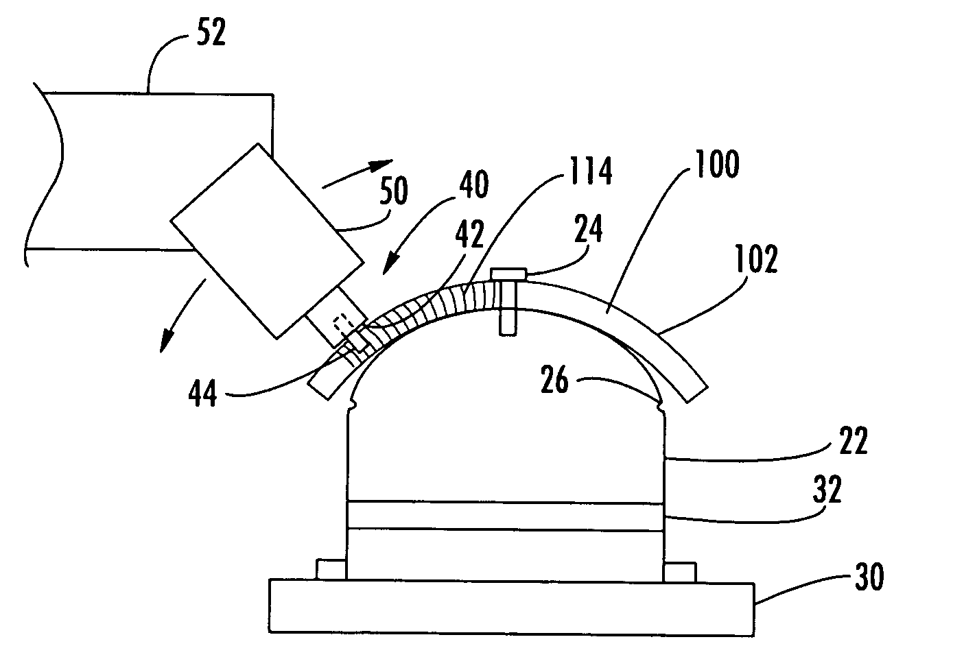
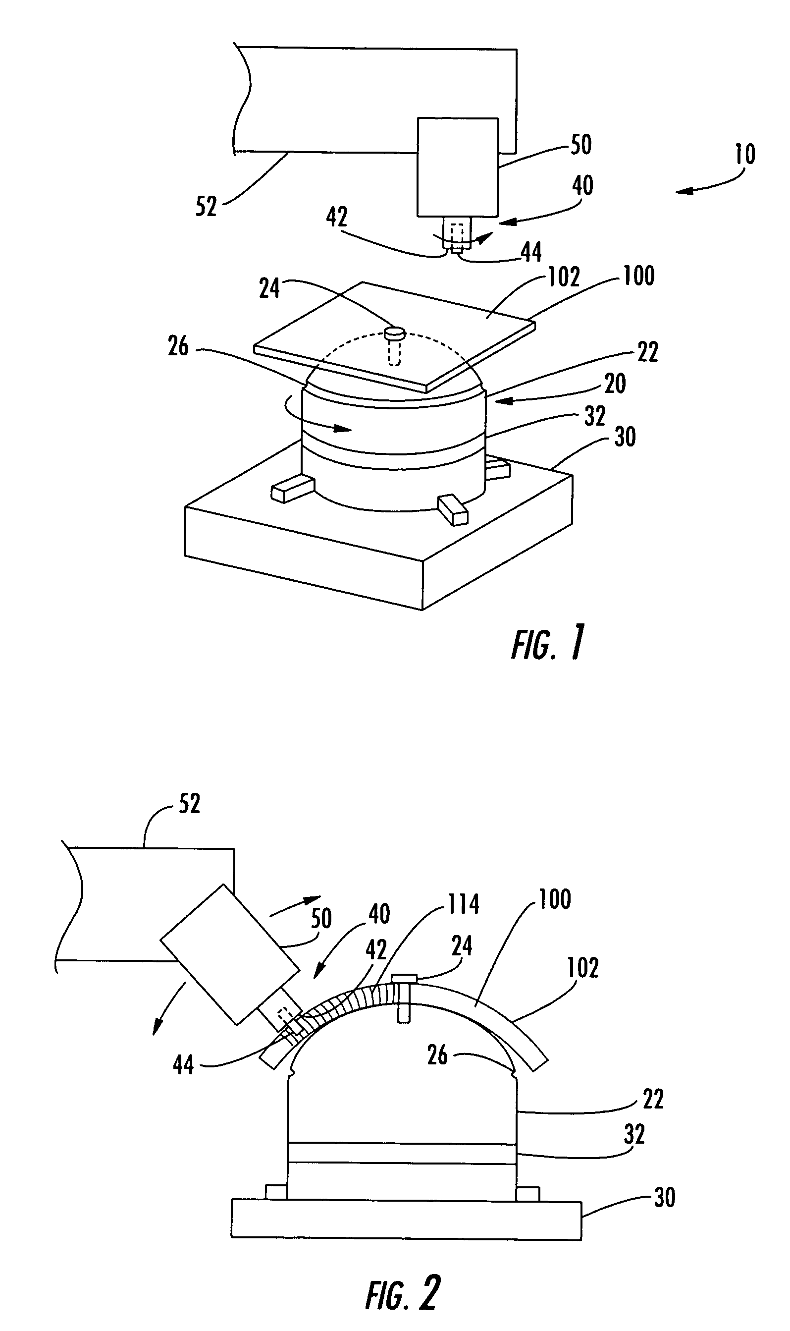
[0020]Referring now to the drawings, and in particular to FIG. 1, there is shown an apparatus 10 for forming a workpiece 100 to a desired configuration. The workpieces 100 can be formed of metal, such as steel, aluminum, titanium, or alloys thereof, polymers, and other materials that are compatible with friction stir processing. The workpieces 100 can be used for a variety of applications including, but not limited to, structural panels, brackets, tubes, caps, and the like. For example, a dome-shaped workpiece 100...


PUM

PropertyMeasurementUnit
grain structureaaaaaaaaaa
thicknessaaaaaaaaaa
shapeaaaaaaaaaa

Abstract

An apparatus and method for forming a workpiece to a desired, non-planar configuration are provided. At least one friction stir forming tool, having a shoulder and a pin, is used to urge the workpiece to the desired configuration and friction stir form the workpiece. The forming tool can urge the workpiece against a contour surface of a die or a shoulder that is opposite the structural member from the tool. Thus, the forming tool plasticizes a portion of the workpiece and urges the workpiece to the desired configuration. In addition, the material properties of the workpiece can be improved by the friction stir processing.

Description

BACKGROUND OF THE INVENTION[0001]1) Field of the Invention[0002]The present invention relates to the forming of structural members and, more particularly, to the forming of structural members in conjunction with friction stir processing.[0003]2) Description of Related Art[0004]The forming of structural members to desired shapes can be accomplished by forging, stamping, bending, machining, and the like. For example, a preform or blank comprising a flat sheet of metal such as steel, aluminum, titanium, or alloys thereof can be heated in a forge and hammered to the desired shape of the member. Alternatively, a mechanical or hydraulic press can be used to stamp or forge the structural member to the desired shape, e.g., between two opposing dies that define forming surfaces that correspond to the desired contour of the member. Such forming methods are typically quicker and less expensive than casting molten material in the desired shape, and complex shapes can be imparted to the member, ...

Claims


Application Information

Patent Timeline
Patent Type & Authority Patents(United States)
IPC IPC(8): B23K20/12B21D11/20B21D5/00B21D22/16B21D31/00B29C67/00
CPCB21D22/16B23K20/126B23K20/1275B23K20/12B21D5/00
Inventor FORREST, ROBERT S.WALDRON, DOUGLAS J.
Owner THE BOEING CO
Why Eureka
Try Eureka