Apparatus and method for forming a weld joint having improved physical properties

a technology of weld joints and apparatus, which is applied in the direction of resistance welding apparatus, arc welding apparatus, metal-working apparatus, etc., can solve the problems of reducing the yield strength of plasticized parent materials, forming tensile residual stresses in workpieces, and limited welding applications for certain manufacturing processes. achieve the effect of improving the material properties of the final produ

Inactive Publication Date: 2005-10-13
SURFACE TECH HLDG
View PDF8 Cites 39 Cited by
  • Summary
  • Abstract
  • Description
  • Claims
  • Application Information

AI Technical Summary

Benefits of technology

[0013] The novel method of forming a weld joint of the present invention comprises the steps of performing a welding operation along a weld line to join two or more workpieces together; and performing a compression operation to induce a deep layer of compression in the surfaces of the workpieces to improve the material properties of the final product. In a preferred embodiment of the invention, the welding operation forms regions of elevated surface temperature along the workpieces, and the compression operation is performed along the regions to produce deep compression.

Problems solved by technology

Unfortunately, several significant problems have limited the application of welding for certain manufacturing processes.
One problem generally associated with welding is that the temperature required to melt or plasticize the parent materials typically reduces their yield strength.
Another common problem associated with welding is the formation of tensile residual stresses created in the workpieces during the welding process by the expansion and then contraction of the fusion or plasticized zoned and regions adjacent to the weld joint.
Such tensile residual stresses are well known to reduce both fatigue life and increase sensitivity to corrosion-fatigue and stress corrosion cracking in a wide variety of materials.
Another problem associated with many welding processes is the production of flash or excess material at the edge of the fusion or stir zone.
Unfortunately, until now, there is no direct and cost effective method of restoring yield strength and improving the corrosion resistance of a weld joint.
While acceptable corrosion resistance can be achieved by post-weld induction heat treatment, this technique is economically and technically impractical for all but the smallest and simplest of geometric shapes.
Induction heating is also not easily controlled spatially and often results in overheating the material around the weld.
While tensile stresses may be reduced or eliminated, compressive stresses are not easily induced by heat treatment techniques, except in special cases such as internally cooled tubular (pipe) weldments.
Other material properties, such as yield strength, are also difficult to improve.
Further, local heating by induction, or other means, can result in distortion and an increase tensile residual stresses elsewhere in the workpiece.
However, such coatings also require a second independent process, which significantly increases the cost and production time.
Further, such coatings provide only a superficial protective layer and do not protect surfaces that cannot be accessed, and protection of the surface is lost if the coating is broken or deteriorates during service.
Unfortunately however, excess cold working may produce tensile surface stresses or spalling damage and may leave the surface susceptible to overload and thermal relaxation.
While shot peening and gravity peening may be used for inducing compressive residual stresses along the surface of the weld joint, unfortunately, shot peening and gravity peening also impart an uncontrolled amount of cold work making it difficult to optimize the physical properties of the weld.
Further, the degree of cold working of the material by shot peening or gravity peening is relatively high, which may be undesirable for many applications.
The shot or gravity peening induced compressive residual stresses are relatively shallow, affording limited benefit in arresting fatigue or stress corrosion cracks because the shallow compressive layer may be lost to wear or corrosion in service.
Shot peening and gravity peening also produce a poor surface finish further making the processes unacceptable for many applications.
It is also known that the beneficial effects produced by shot peening and gravity peening are generally lost as the pattern of compression relaxes with time in elevated temperature service.
It should now be apparent that until now, in addition to the problems identified above, all post welding procedures have required a second-pass process that significantly adds to the cost of manufacturing, since it takes more time and effort to produce a finished part than the time required for those parts not needing post welding treatment.
Depending on the size, or number of parts, or the location of the weld, such increase in time and cost associated with a second-pass process often makes post-welding treatment impractical.
In addition, until now, such methods for inducing compressive stress along the surface of a joint line in a prescribed pattern have not been used as a facet of the welding process.

Method used


Image

  • Apparatus and method for forming a weld joint having improved physical properties
  • Apparatus and method for forming a weld joint having improved physical properties
  • Apparatus and method for forming a weld joint having improved physical properties

Examples


Embodiment Construction

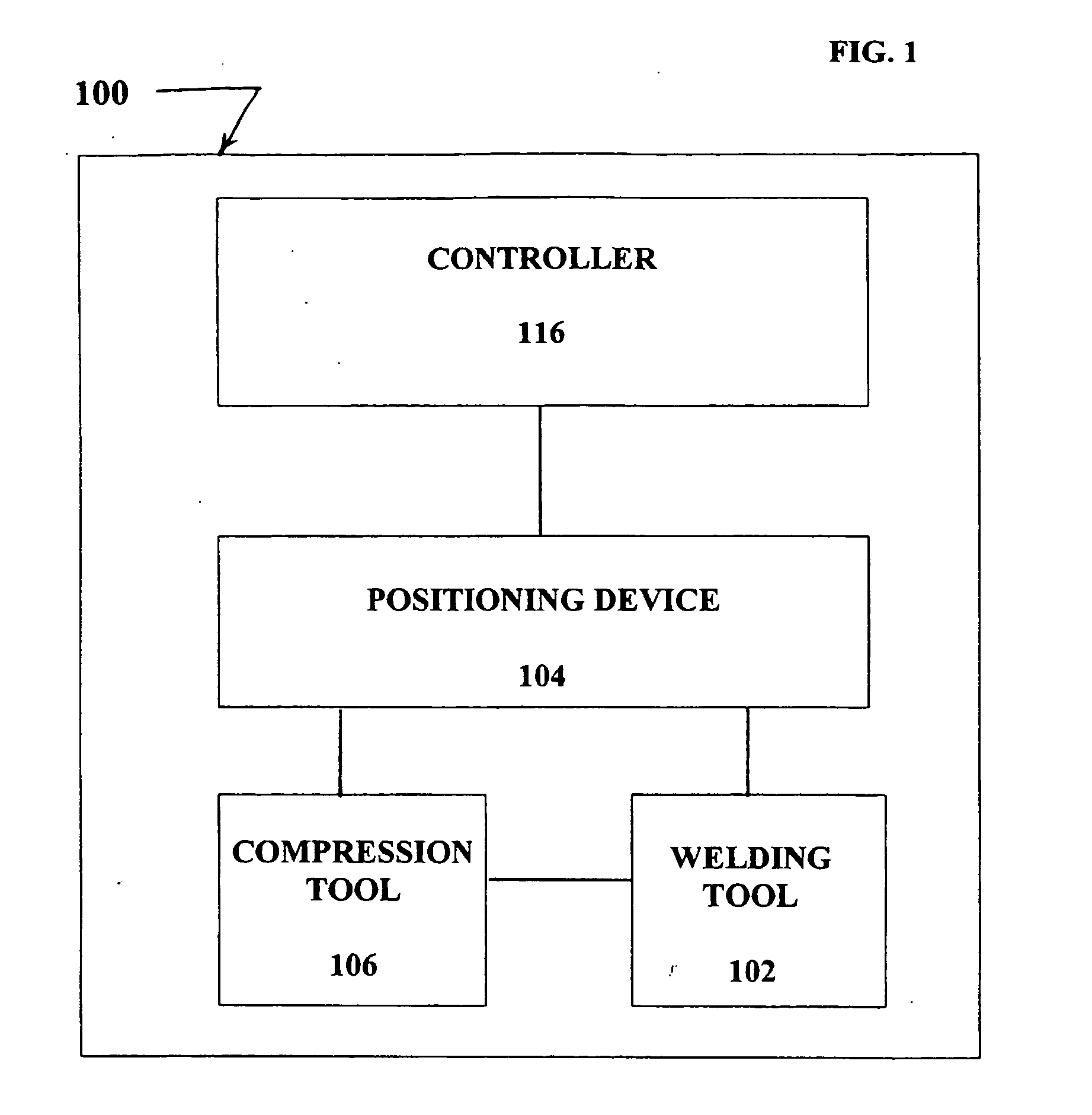
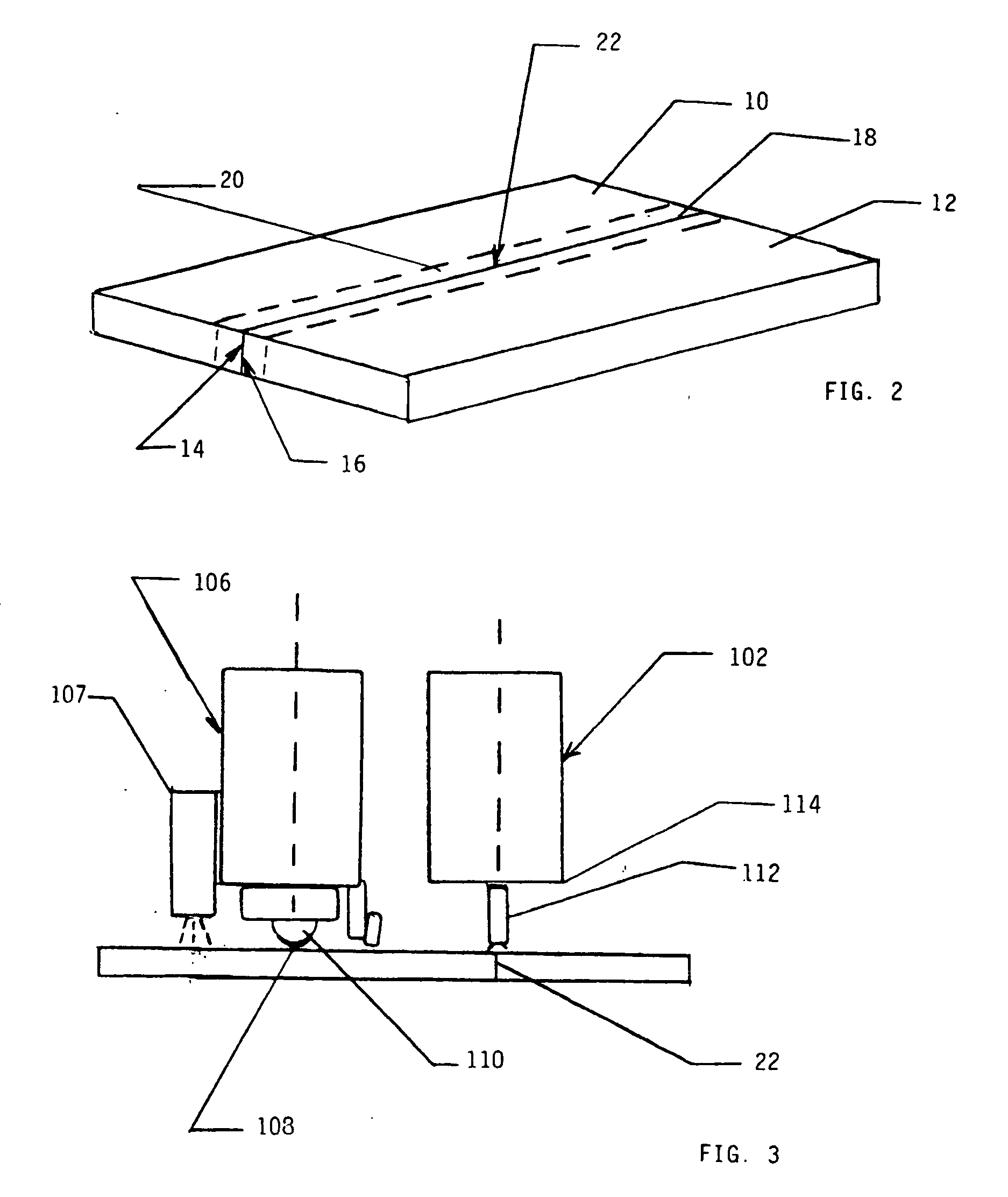
[0055] The present invention is directed to a new and novel method and apparatus for performing the method of forming a weld joint and, a more particularly, a method and apparatus for forming a weld joint which utilizes a controlled process of inducing a specific compressive residual stress pattern and degree of cold working and surface hardening along a weld line to improve the physical properties of the weld joint and the resulting final product. In a preferred embodiment of the invention, the welding apparatus comprises a welding tool for welding one or more workpieces, and a compression tool for inducing a layer of residual compressive stress in the surface of a workpiece. In another preferred embodiment of the invention, the method utilizes a process of inducing a specific and selected pattern of compressive residual stress and selected amount of cold working and surface hardening, such as by the process of controlled low plasticity burnishing, to improve the physical propertie...


PUM

PropertyMeasurementUnit
temperatureaaaaaaaaaa
surface temperatureaaaaaaaaaa
compressive stressaaaaaaaaaa

Abstract

The method and apparatus for performing the method of forming a weld joint of the present invention utilizes welding apparatus (100) having welded tool (102) and a compression tool (106) for inducing a layer of residual compressive stress along the surface of the weld line (18) and any heat affected regions with a controlled amount of cold working and surface hardening. In a preferred embodiment of the invention the compression tool (106) utilizes a single-point burnishing process to provide deep compression within the weld joint (20) with a minimal amount of cold working and surface hardening.

Description

CROSS REFERENCE TO RELATED APPLICATION [0001] This application claims benefit of International Application No. PCT / US02 / 35214 filed Nov. 1, 2002, under the Patent Cooperation Treaty and to U.S. Provisional Application No. 60 / 367,623 filed Mar. 26, 2002.TECHNICAL FIELD [0002] This invention relates to an apparatus and a method for forming a weld joint having improved physical properties and, more particularly, to a method of forming a weld joint utilizing a controlled method of inducing a specific compressive residual stress pattern and degree of cold working along the welding line to improve the physical properties of the weld. BACKGROUND OF THE INVENTION [0003] In the manufacture and construction of many types of structures, welding, such as gas welding, arc welding, resistance welding, thermite welding, laser welding, and electron-beam welding, has reduced or replaced the use of various types of fastening methods, such as bolting, riveting and the like. Such welding techniques eit...

Claims


Application Information

Patent Timeline
Patent Type & Authority Applications(United States)
IPC IPC(8): B23K9/00B23K11/00B23K23/00B23K26/20B23K28/00C21D7/04C21D7/08C21D9/50
CPCB23K9/00B23K11/00B23K23/00B23K2203/04B23K2203/10B23K26/26C21D7/04C21D7/08C21D9/50C21D9/505B23K2203/14B23K2103/04B23K2103/10B23K2103/14
Inventor PREVEY, PAUL S
Owner SURFACE TECH HLDG
Why Eureka
Try Eureka