Composite armor having a layered metallic matrix and dually embedded ceramic elements

Active Publication Date: 2010-11-16
UNITED STATES OF AMERICA SEC OF THE NAVY CHIEF OF NAVAL RES OFFICE OF COUNSEL ATTN CODE OOCIP THE
View PDF38 Cites 37 Cited by
  • Summary
  • Abstract
  • Description
  • Claims
  • Application Information

AI Technical Summary

Benefits of technology

[0007]In view of the foregoing, an object of the present invention is to provide a metal matrix composite armo

Problems solved by technology

These conventional armor systems are becoming prohibitively heavy in order to protect vehicles from increasingly formidable attack capabilities.

Method used


Image

  • Composite armor having a layered metallic matrix and dually embedded ceramic elements
  • Composite armor having a layered metallic matrix and dually embedded ceramic elements
  • Composite armor having a layered metallic matrix and dually embedded ceramic elements

Examples


Embodiment Construction

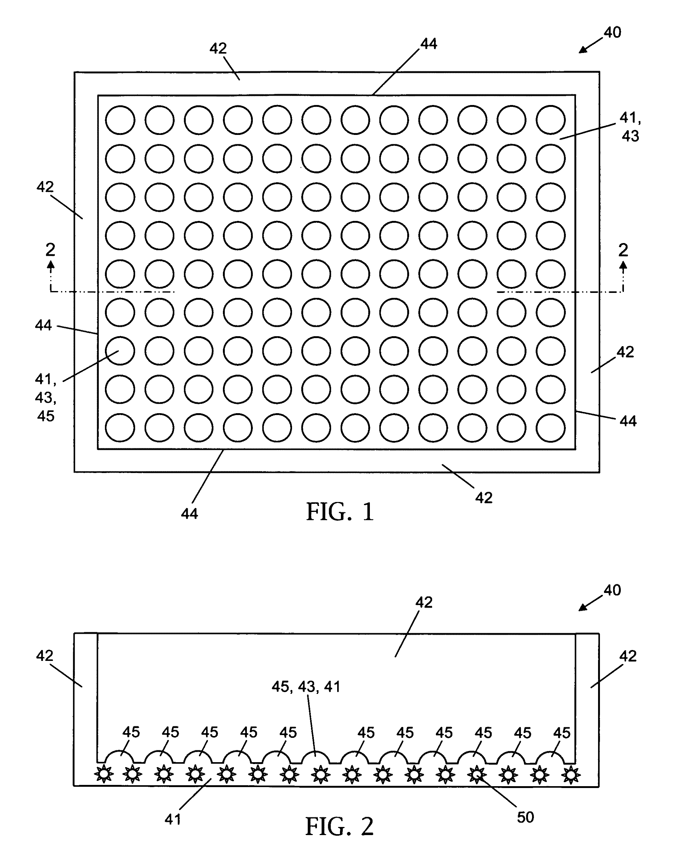
[0053]Referring now to FIG. 1 and FIG. 2, steel tray-like mold 40 includes a horizontal base plate portion 41 and four vertical wall portions 42. The inside surfaces of mold 40 include the “pimpled” upper surface 43 of horizontal base plate portion 41 and the respective smooth (even) side surfaces 44 of vertical wall portions 42. The pimpled upper surface 43 of base plate portion 41 is characterized by a regular pattern of congruent elevations 45, each of which describes the geometric shape of a sphere that is horizontally truncated below its apex, at or above its horizontal planar bisector. Associated with mold 40 (for instance, coupled with base plate portion 41) are heating devices 50.

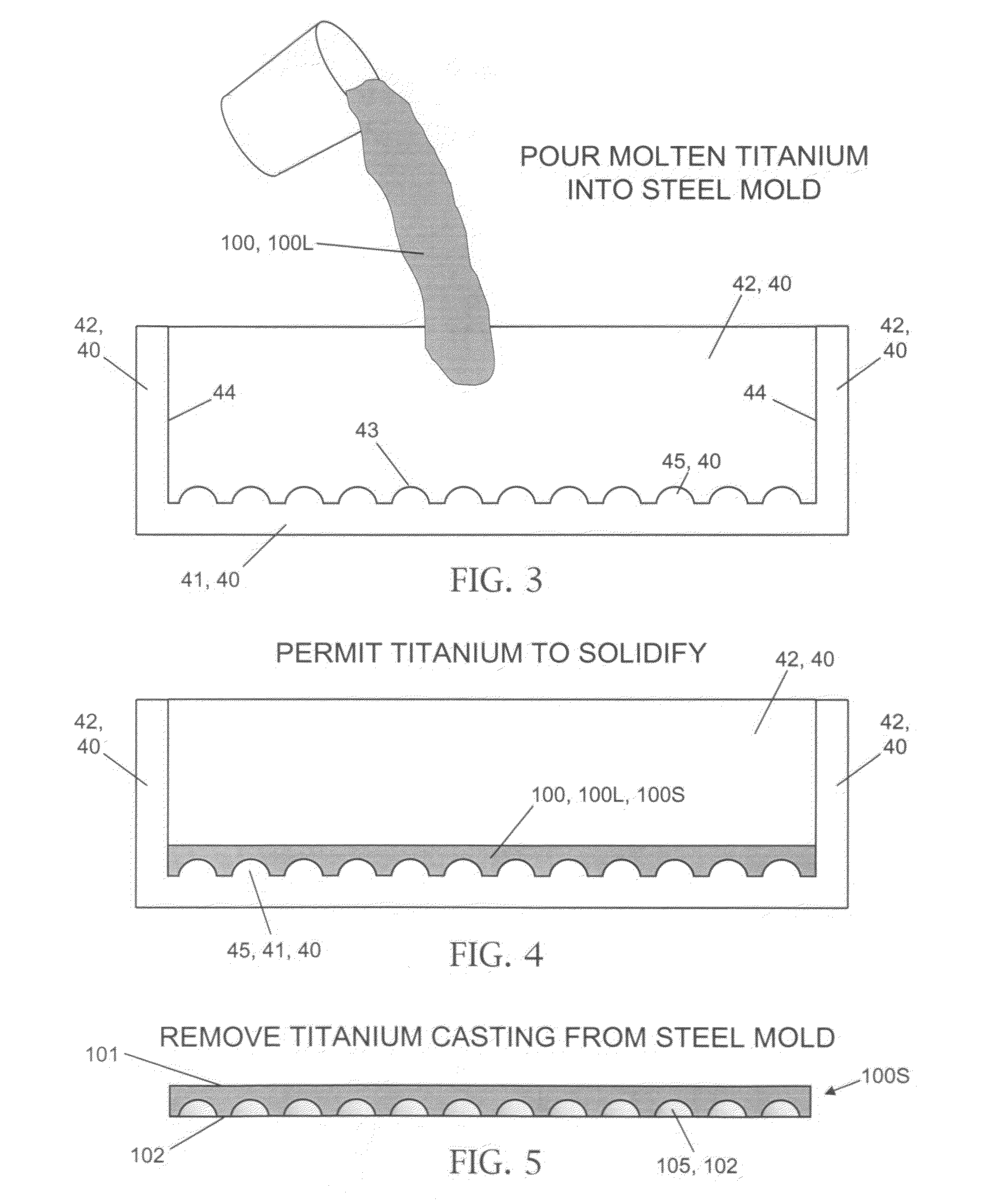
[0054]With reference to FIG. 3 through FIG. 9, the interior surfaces (including upper surface 43 and side surfaces 44) of mold 40 are coated, as appropriate, with a mold release agent (e.g., zirconium oxide or zirconia). Heating devices 50 serve to extremely raise the temperature of mold 40 and ther...


PUM

PropertyMeasurementUnit
Diameteraaaaaaaaaa
Metallic bondaaaaaaaaaa
Melting pointaaaaaaaaaa

Abstract

According to typical inventive practice, a first metallic material is poured into a mold including a bottom inside surface having regularly arrayed rises (truncated spherical convexities). The molten first metallic material cools and solidifies to include a surface correspondingly having regularly arrayed dents (truncated spherical concavities). The resultant “inner casting” is removed from and repositioned in the mold so that the inner casting's dent-laden surface faces upward. Ceramic spheres are placed in the dents. A second metallic material (having a higher melting point than the first metallic material) is poured into the mold with the inner casting and spheres in place. The molten second metallic material cools and solidifies as an “outer casting” surrounding the inner casting and the spheres. The resultant integral armor structure includes the inner casting, the outer casting, and the spheres, each sphere embedded partially in the inner casting and partially in the outer casting.

Description

STATEMENT OF GOVERNMENT INTEREST[0001]The invention described herein may be manufactured and used by or for the Government of the United States of America for governmental purposes without payment of any royalties thereon or therefor.BACKGROUND OF THE INVENTION[0002]The present invention relates to ballistic armor systems, more particularly to composite ballistic armor systems that include a metallic matrix and one or more metallic or non-metallic elements contained therein.[0003]Military armor applications include land, air and sea vehicles, stationary structures, and personnel. The need for lighter weight and more effective armor plating for protecting various military vehicles is ongoing, especially as enemy munitions become increasingly powerful. Protection of the vehicles and their occupants is needed against impact by a projectile such as a ballistic body (e.g., small arms fire) or an explosive fragment (e.g., shrapnel from a bomb blast). Conventional metal vehicle armor syste...

Claims


Application Information

Patent Timeline
IPC IPC(8): F41H5/04
CPCF41H5/0442F41H5/0492Y10S428/911Y10T428/31522
Inventor FERRANDO, WILLIAM A.
Owner UNITED STATES OF AMERICA SEC OF THE NAVY CHIEF OF NAVAL RES OFFICE OF COUNSEL ATTN CODE OOCIP THE
Why Eureka
Try Eureka