System for Optimizing Electricity Use from an Electric Grid and Related Method

a technology of optimizing electricity use and electric grid, applied in the direction of charging stations, transportation and packaging, instruments, etc., can solve the problems of not being able to achieve the perfect valley filling solution from equations (1), (2), and (4), and not being able to prevent intermittent charging profiles,

Active Publication Date: 2016-01-14
RGT UNIV OF CALIFORNIA
View PDF10 Cites 35 Cited by
  • Summary
  • Abstract
  • Description
  • Claims
  • Application Information

AI Technical Summary

Problems solved by technology

Although the situation of having the deepest valley in the afternoon may not happen often, it underlines the point that the ability of PEVs to alter electric load significantly may be somewhat limited to the overnight period.
Naturally, a perfect valley filling solution from Equations (1), (2), and (4) may not be difficult to achieve depending on the specific shape of the net load, the availability of the PEVs, and the individual level charge needs.
i.e., shifting the charging to the tj′ time slot reduces the cost, which is not possible as it contradicts the optimality of the solution.
It is noted that the present implementation does not prevent intermittent charging profiles, which can happen if the apparent cost to the PEV has multiple local (and similar in depth) peaks and valleys.
Peak 708 on curve 706 may expose a significant extra burden on the grid, thus undesirable.
Forcing continuous charging inevitably leads to a sizable number if PEVs having overlapping charging time, resulting in the shape seen in FIG. 12A.
It is noted that none of the existing research has addressed this since they require that most PEVs arrived home to initiate the protocol, often quite late in the day, e.g. midnight.
Naturally, it is difficult to fill the afternoon valley in practice.
When there exists a relatively large valley (or multiple valleys) in the afternoon due to large solar / wind generation (or intermittent solar / wind generation), it may lead a scenario, in which power plants have to ramp up and down quickly to meet this particular load, increasing cost and generating more emissions or, alternatively, some of the solar / wind power is curtailed.
This modification, see Equation (15), results in a cost function that is essentially the gap between the current load and the target load.
However, by then there might not be enough PEVs available to fill the first gap, as the results show in FIG. 17.
Third, for the first gap, from hour 11:00 to hour 18:00, the same problem discussed earlier can exist, that early PEVs may fill the deepest point, at around hour 15:00, and only then the rest of the gap.
When the number of PEVs is small, there is a possibility that sufficient PEVs are not available to fill the early part of the gap.
The results presented in the present application may lead to intermittent charging.

Method used


Image

  • System for Optimizing Electricity Use from an Electric Grid and Related Method
  • System for Optimizing Electricity Use from an Electric Grid and Related Method
  • System for Optimizing Electricity Use from an Electric Grid and Related Method

Examples


Embodiment Construction

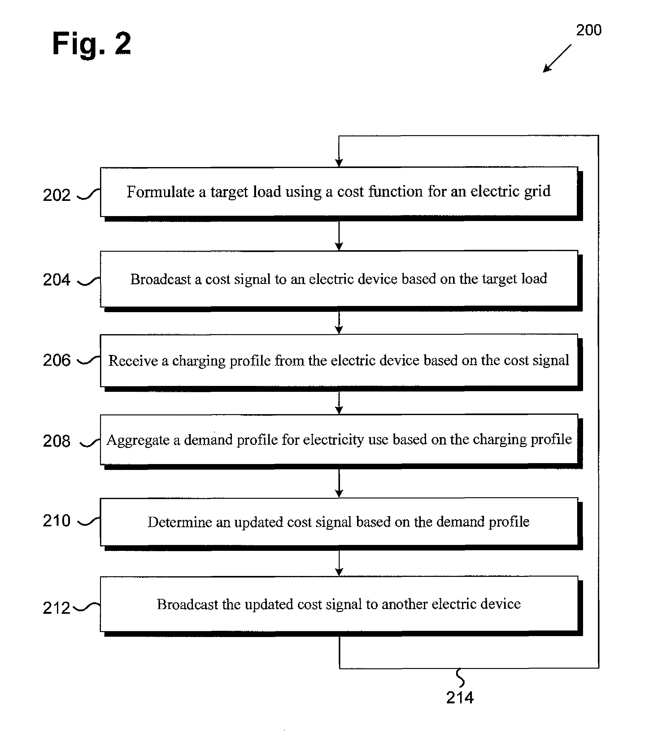
[0029]The following description contains specific information pertaining to implementations in the present disclosure. The drawings in the present application and their accompanying detailed description are directed to merely exemplary implementations. Unless noted otherwise, like or corresponding elements among the figures may be indicated by like or corresponding reference numerals. Moreover, the drawings and illustrations in the present application are generally not to scale, and are not intended to correspond to actual relative dimensions.

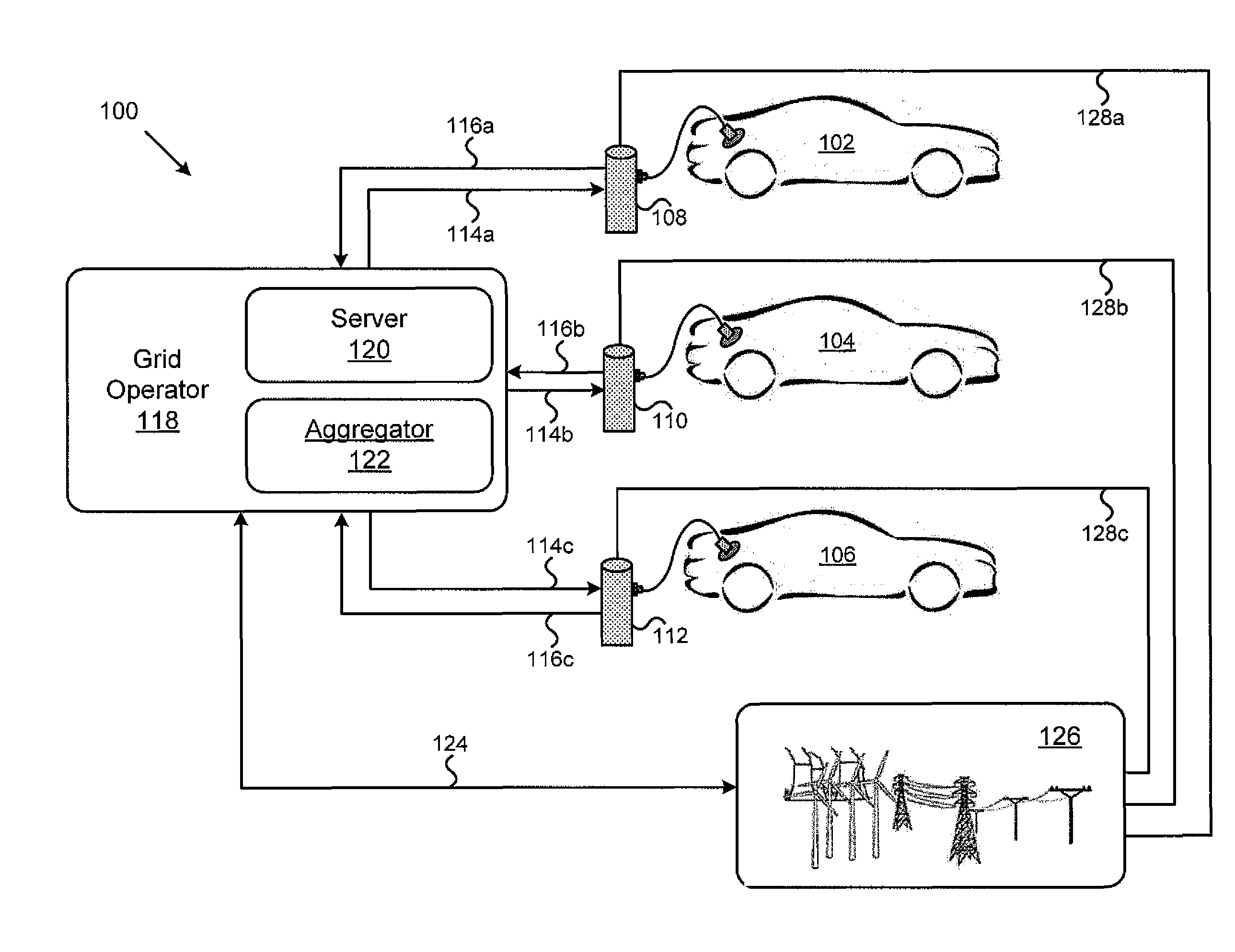
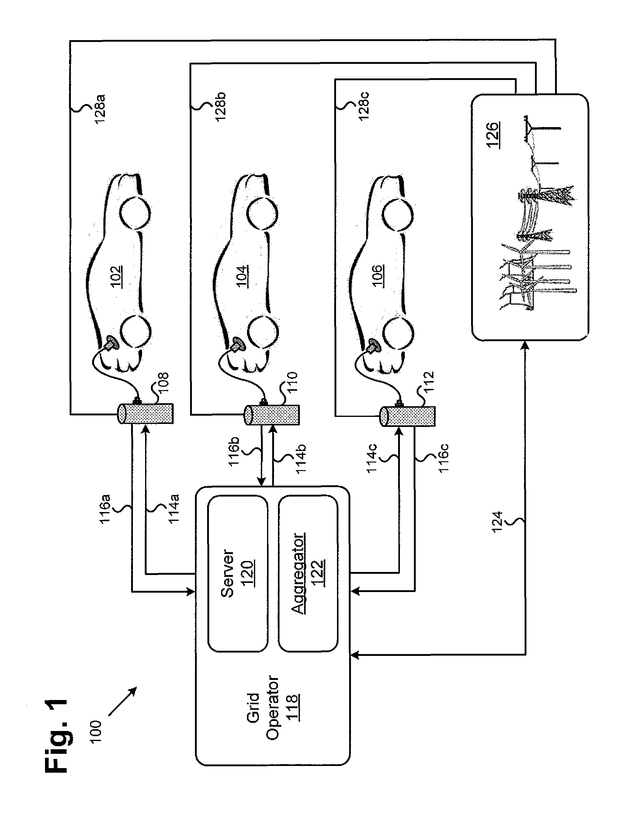
[0030]FIG. 1 illustrates an exemplary system of optimizing electricity use from an electric grid, according to one implementation of the present application. As illustrated in FIG. 1, exemplary system 100 for optimizing electricity use from an electric grid includes electric devices 102, 104 and 106, charging stations 108, 110 and 112, grid operator 118 having server 120 and aggregator 122, electric grid 126. In the present implementation, elec...


PUM


Abstract

A method of optimizing electricity use from an electric grid is disclosed. The method includes formulating a target load using a cost function for the electric grid, broadcasting a cost signal to the electric device based on the target load, receiving a charging profile from the electric device based on the cost signal, aggregating a demand profile for the electricity use based on the charging profile, determining an updated cost signal based on the demand profile, and broadcasting the updated cost signal to another electric device. The electric device is chargeable electric device, such as a plug-in electric vehicle (PEV). The electric device determines the charging profile only once based on the cost signal, and is charged at maximum power.

Description

[0001]The present application claims the benefit of and priority to a provisional patent application entitled “Coordinating Plug-in Electric Vehicle Charging with Electric Grid,” Ser. No. 62 / 023,754 filed on Jul. 11, 2014. The disclosure in this provisional application is hereby incorporated fully by reference into the present application.STATEMENT OF GOVERNMENT INTEREST[0002]This invention was made with Government support under Contract No. N660001-1-2-4041, awarded by the DARPA. The Government has certain rights in this invention.BACKGROUND[0003]Plug-in electric vehicles (PEVs), such as plug-in hybrid electric vehicles (PHEVs) and battery electric vehicles (BEVs), have drawn interest from state and local governments, automakers, and the general public due to the potential to reduce fossil fuel consumption, tailpipe emissions, overall greenhouse gas emissions, and operating cost. For example, the California Advanced Clean Cars program mandates 1.4 million zero-emission and PHEVs in...

Claims


Application Information

Patent Timeline
Patent Type & Authority Applications(United States)
IPC IPC(8): B60L11/18
CPCB60L11/1816B60L11/1848G06Q50/06Y02T10/7072Y02T90/14Y04S30/14G06Q20/145G07F15/005B60L53/64B60L53/665Y02T90/12Y02T90/167Y02T10/70Y02T90/16
Inventor ZHANG, LIJABBARI, FARYARSAMUELSEN, SCOTT
Owner RGT UNIV OF CALIFORNIA
Why Eureka
Try Eureka