Thin luminaire

a technology of light emitting diodes and luminaires, which is applied in the direction of identification means, lighting and heating apparatus, instruments, etc., can solve the problems of limited emission patterns and notable limitations, and achieve the effects of excellent color mixing, high utilization factor of present luminaires, and inability to easily adjust the spectrum of lamps

Active Publication Date: 2016-01-14
SEOUL SEMICONDUCTOR
View PDF14 Cites 55 Cited by
  • Summary
  • Abstract
  • Description
  • Claims
  • Application Information

AI Technical Summary

Benefits of technology

[0014]In lighting applications that require excellent color mixing with tight beam control, embodiments of the present luminaire can excel. Embodiments of the present luminaires have significant advantages if used as a downlight or troffer. The luminaires can be made into thin panels, which can be installed in the ceiling, having the same dimension as troffers which use fluorescent tubes. The typical efficiency of the luminaires used in previously proposed troffers is on the order of 70%. Also these prior luminaires do not have the tight beam control that is possible with the present luminaires. A

Problems solved by technology

The luminaires of U.S. Pat. No. 7,806,547 are mainly aimed at producing backlights, and for that reason, have some notable limitations

Method used


Image

  • Thin luminaire
  • Thin luminaire
  • Thin luminaire

Examples


embodiment 200

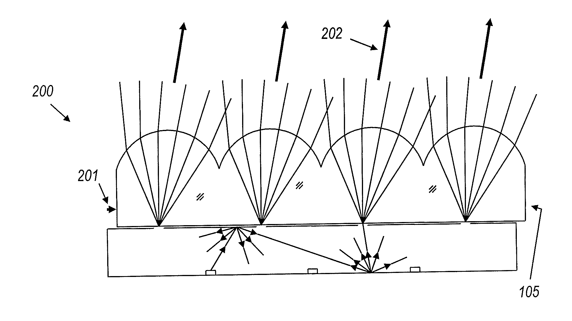
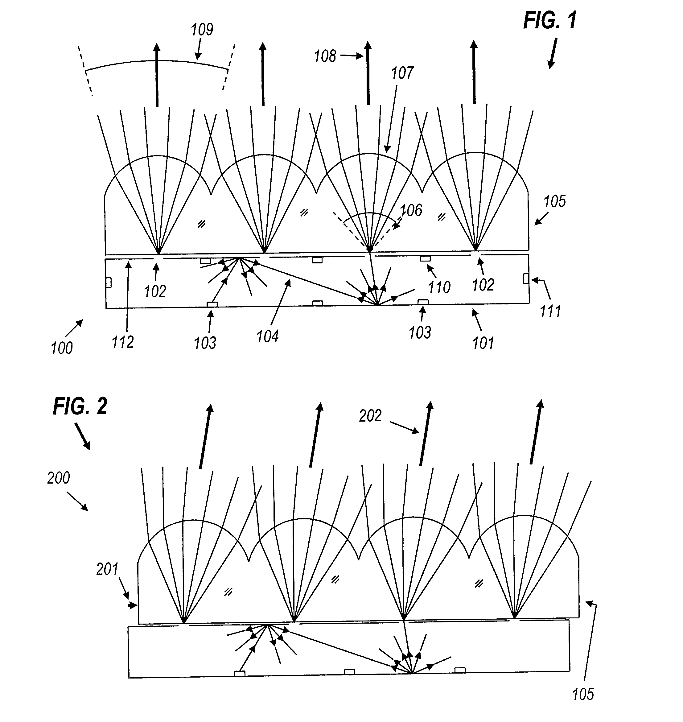
[0043]FIG. 2 shows an embodiment 200 of a luminaire as a beam steering device. It is similar to the device in FIG. 1 except that top optic 105 is movable relative to the holes 102 in the perforated sheet forming the top wall of mixing chamber 101, and may slide sideways by a displacement 201. This results in an angular displacement of the emission pattern, which now exits in direction 202. Because of refraction where the light enters the bottom surface of optic 105, the light proceeds from each hole 102 to the respective lens 107 in a conical beam, the cone angle 106 of which is determined by the critical angle at the bottom surface of optic 105, and therefore by the refractive index of the material of optic 105. The optic 105 is made thin enough that the conical beams from adjacent holes 102 do not meet within the optic 105. The gap between adjacent beams is larger than the maximum travel 201 of the optic 105, so that each conical beam is entirely captured by its respective lenslet...

embodiment 500

[0047]FIG. 5A shows embodiment 500 which is a similar device to that in FIG. 4 but now with specially shaped holes 504 in sheet 502. This shaping of the holes may be used to generate a special pattern, for example that of a low beam automotive headlamp. Edges 506 and 508 of the holes have different shapes facilitating the process of generating the desired pattern output.

[0048]Referring to FIG. 5B, in a further modification 520 of the device of FIG. 5A, the holes 524, 526 may be provided with liquid crystal device (LCD) or other switchable arrays 522, so that the effective shapes of the holes 504 can be changed electronically, even when the luminaire 500 is in use. These LCDs have the ability to either “open” the holes (letting light through) or “close” the holes (reflecting part of the light back) in response to electrical inputs. It is presently preferred to provide a separate small LCD array for each hole 524, 526, with the space in between being solid, highly reflective material,...


PUM


Abstract

A luminaire includes a mixing chamber having an array of apertures in one wall, a light source to supply light into the mixing chamber, and an array of optics outside the mixing chamber, each positioned to cooperate with a respective one of the apertures to emit light from the mixing chamber as a beam. The shape, size, and/or direction of the output light beam are controllably varied by controlling the shape, size, and/or position of each aperture relative to its associated optic.

Description

CROSS-REFERENCE TO RELATED APPLICATION[0001]Priority is hereby claimed to U.S. Provisional Patent Application No. 61 / 851,611, filed Mar. 12, 2013, entitled Ultra-Thin Luminaire, which is incorporated by reference herein in its entirety.[0002]Reference is made to U.S. Pat. No. 7,806,547, which has several inventors in common with the present invention and which is incorporated by reference herein in its entirety.[0003]Part of the research / work leading to these results was supported by the European Union's Seventh Framework Programme (FP7 / 2007-2013) under Grant Agreement no 619912.FIELD OF THE INVENTION[0004]The present methods and apparatus relate generally to light-emitting diodes (LEDs) and other light sources, and more particularly to light collection / distribution systems that utilize and array of light sources.BACKGROUND[0005]U.S. Pat. No. 7,806,547 describes a backlight composed of a mixing chamber with LEDs and holes through which light escapes. This light is then captured by a...

Claims


Application Information

Patent Timeline
IPC IPC(8): F21K99/00F21S8/04F21S8/10F21V13/04
CPCF21K9/54F21S48/1317F21Y2101/02F21V13/04F21S8/04F21S41/143F21S41/153F21S41/265F21S41/43F21S41/645F21V5/007F21V11/14F21V11/186F21Y2105/10F21Y2107/20F21Y2115/10G09F9/33G09F2013/222
Inventor BENITEZ, PABLOMINANO, JUAN CARLOSMOHEDANO, RUBENCHAVES, JULIO C.FALICOFF, WAQIDI
Owner SEOUL SEMICONDUCTOR
Why Eureka
Try Eureka