
Thin-type common mode filter and manufacturing method thereof

a filter and common mode technology, applied in the direction of magnets, inductances, magnetic bodies, etc., can solve the problem of more likely micro cracks at the interface between the substrate and the micro cracks, and achieve the effect of increasing the adhesion of the interfa

Inactive Publication Date: 2016-01-14
SAMSUNG ELECTRO MECHANICS CO LTD
View PDF11 Cites 6 Cited by
  • Summary
  • Abstract
  • Description
  • Claims
  • Application Information

AI Technical Summary

Benefits of technology

The patent aims to improve the adhesion between a ferrite substrate and an insulating layer in a thin-type common mode filter to enhance its performance in high-temperature and humidity environments. This will ensure the reliability of the filter's electrical and mechanical properties.

Problems solved by technology

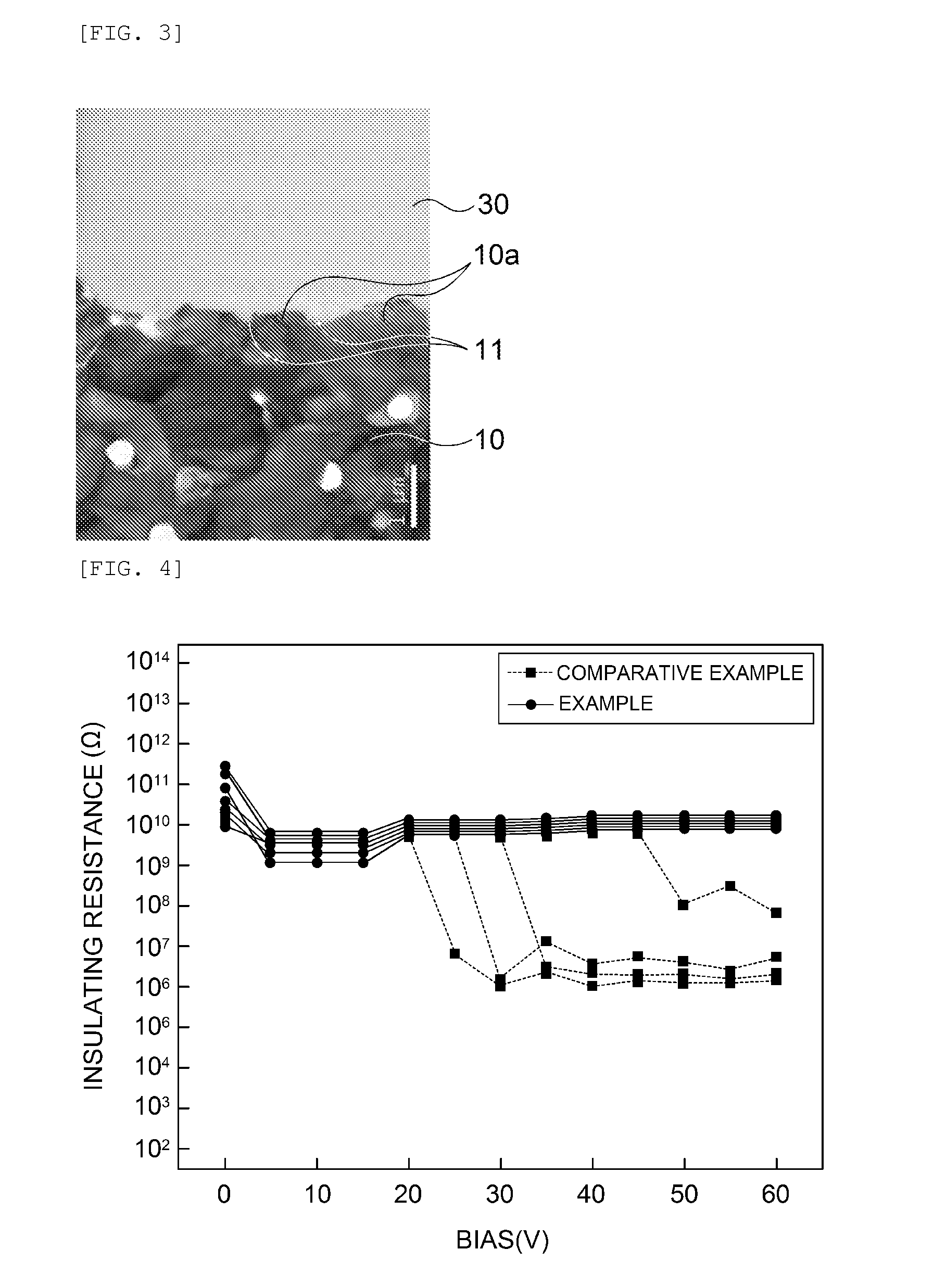
When a load above a certain voltage is applied under the high temperature / humidity environment of the existing thin-type common mode filter, micro cracks are more likely to occur at the interface between the substrate having structural weaknesses and the insulating layer than at other portions.

Method used


Image

  • Thin-type common mode filter and manufacturing method thereof
  • Thin-type common mode filter and manufacturing method thereof
  • Thin-type common mode filter and manufacturing method thereof

Examples


Embodiment Construction

[0029]Exemplary embodiments of the present invention for accomplishing the above-mentioned objects will be described with reference to the accompanying drawings. In the description, the same reference numerals will be used to describe the same components of which a detailed description will be omitted in order to allow those skilled in the art to understand the present invention.

[0030]In the specification, it will be understood that unless a term such as ‘directly’ is not used in a connection, coupling, or disposition relationship between one component and another component, one component may be ‘directly connected to’, ‘directly coupled to’ or ‘directly disposed to’ another element or be connected to, coupled to, or disposed to another element, having the other element intervening therebetween.

[0031]Although a singular form is used in the present description, it may include a plural form as long as it is opposite to the concept of the present invention and is not contradictory in v...


PUM


Abstract

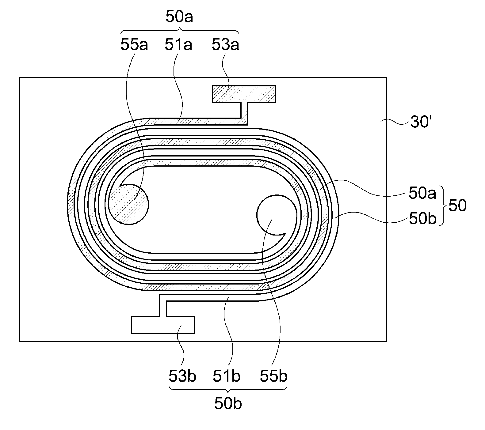
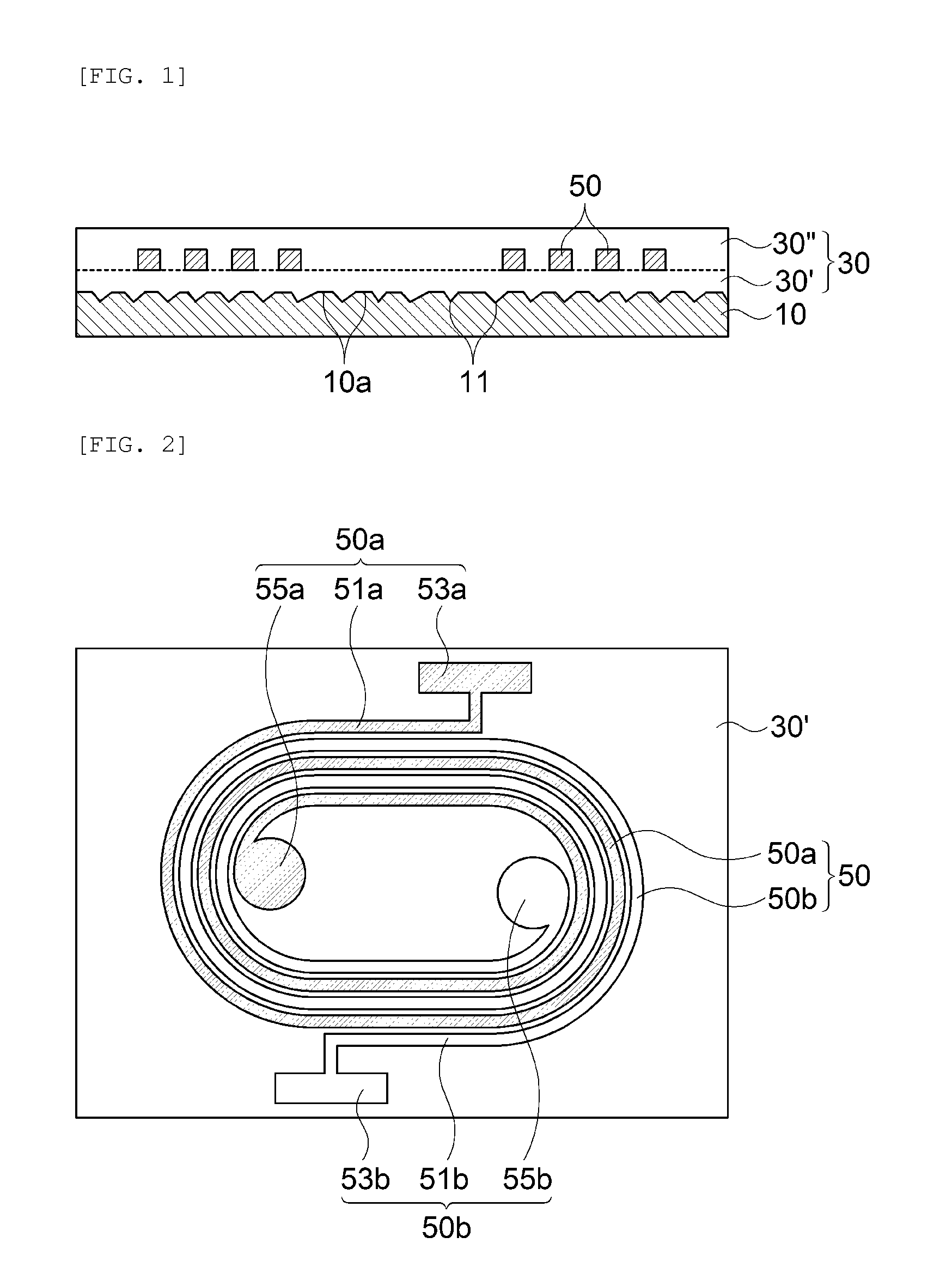
Disclosed herein are a thin-type common mode filter and a manufacturing method thereof. According to an exemplary embodiment of the present invention, a thin-type common mode filter includes: a ferrite substrate having an upper surface on which irregular surface roughness is formed; an insulating layer formed on the upper surface of the ferrite substrate; and a conductive coil pattern formed in the insulating layer to be spaced apart from the upper surface of the ferrite substrate. Further, a manufacturing method of a thin-type common mode filter is proposed.

Description

BACKGROUND OF THE INVENTION[0001]1. Technical Field[0002]The present invention relates to a thin-type common mode filter and a manufacturing method thereof. More specifically, the present invention relates to a thin-type common mode filter and a manufacturing method thereof capable of improving an interface adhesion between a ferrite substrate and an insulating layer.[0003]2. Description of the Related Art[0004]Generally, a thin-type common mode filter (CMF) is formed by coating an insulating layer on a substrate and forming a copper coil thereon by a plating method. The weakest portion of the thin-type common mode filter under high temperature / humidity environment is an interface between the substrate and the insulating layer. By making an adhesion of the interface more excellent than the existing adhesion, reliability may be improved.[0005]In the thin-type common mode filter, since a coil pattern serves as an inductor, for example, the copper coil is formed on the substrate by pla...

Claims


Application Information

Patent Timeline
IPC IPC(8): H01F27/28H01F41/32
CPCH01F41/32H01F27/2804H01F17/0006H01F41/042H01F41/046H01F2017/0093
Inventor YANG, JU HWANYOO, YOUNG SEUCKJANG, GEON SELEE, JONG YUNKWEON, YOUNG DOWI, SUNG KWON
Owner SAMSUNG ELECTRO MECHANICS CO LTD
Learn More