Light emitting module

Inactive Publication Date: 2016-01-14
GENESIS PHOTONICS
View PDF7 Cites 1 Cited by
  • Summary
  • Abstract
  • Description
  • Claims
  • Application Information

AI Technical Summary

Benefits of technology

[0007]The invention is directed to a light emitting module, which has

Problems solved by technology

Generally, when a light emitting diode (LED) emits a light with a high luminance, a large amount of heat is produced.
In this case, the luminance of the LED is probably decreased due to overheat and a service life of the LED is decreased, or even the LED is permanently damaged.
However, after the circuit layout on the circuit board is completed, the serial-parallel connections of the LEDs cannot be easily modified, which is

Method used


Image

  • Light emitting module
  • Light emitting module

Examples


Embodiment Construction

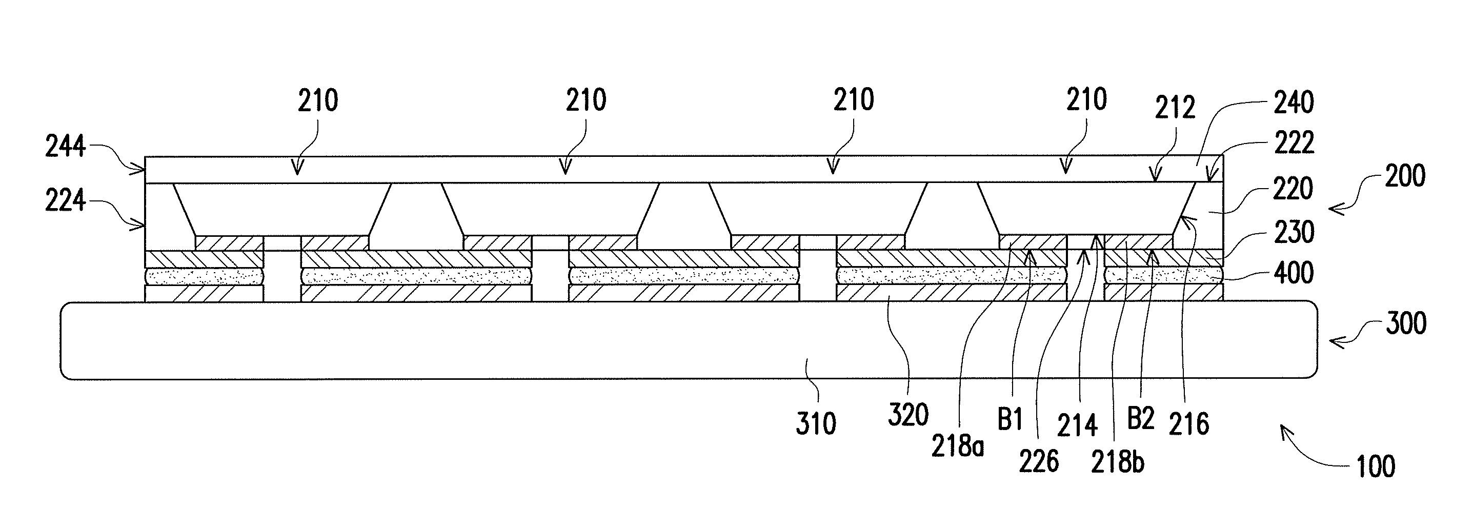
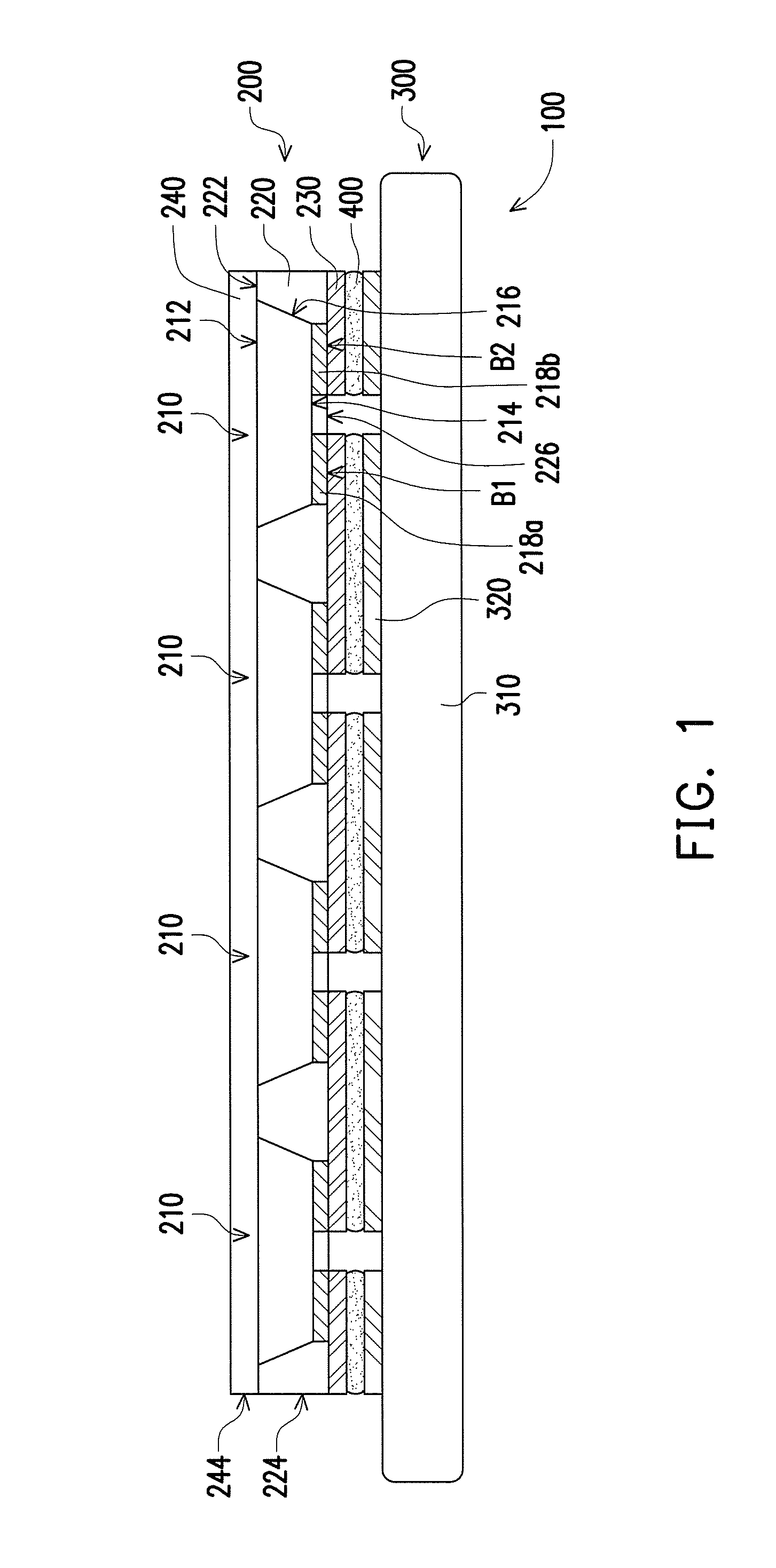
[0022]FIG. 1 is a cross-sectional view of a light emitting module according to an embodiment of the invention. Referring to FIG. 1, the light emitting module 100 includes a light emitting device package structure 200 and a heat dissipation structure 300. The light emitting device package structure 200 includes a plurality of light emitting devices 210, a patterned reflective element 220, a patterned conductive layer 230 and a molding compound 240. The heat dissipation structure 300 is disposed below the light emitting device package structure 200, and includes a heat dissipation unit 310 and a patterned circuit layer 320 disposed on the heat dissipation unit 310.

[0023]In detail, each of the light emitting devices 210 has an upper surface 212 and a lower surface 214 opposite to each other, a side surface 216 connecting the upper surface 212 and the lower surface 214 and a first pad 218a and a second pad 218b located on the lower surface 214 and separated from each other. The patterne...


PUM


Abstract

A light emitting module including a light emitting device package structure and a heat dissipation structure is provided. The light emitting device package structure includes light emitting devices, a patterned reflective element and a patterned conductive layer. The patterned reflective element is disposed around side surfaces of the light emitting devices and exposes a first bottom surface of a first pad and a second bottom surface of a second pad. The patterned conductive layer is disposed on the first bottom surface of the first pad and the second bottom surface of the second pad. The light emitting devices are electrically connected to each other in a series connection, a parallel connection or a series-parallel connection through the patterned conductive layer. The heat dissipation structure is disposed below the light emitting device package structure and includes a heat dissipation unit and a patterned circuit layer disposed on the heat dissipation unit.

Description

CROSS-REFERENCE TO RELATED APPLICATION[0001]This application claims the priority benefit of Taiwan application serial no. 103212473, filed on Jul. 14, 2014. The entirety of the above-mentioned patent application is hereby incorporated by reference herein and made a part of this specification.BACKGROUND OF THE INVENTION[0002]1. Field of the Invention[0003]The invention relates to a light emitting module, and particularly relates to a light emitting module having a good heat dissipation effect and capable of reducing a risk of circuit break.[0004]2. Description of Related Art[0005]Generally, when a light emitting diode (LED) emits a light with a high luminance, a large amount of heat is produced. If the heat cannot escape and is accumulated in the LED, a temperature of the LED is continuously increased. In this case, the luminance of the LED is probably decreased due to overheat and a service life of the LED is decreased, or even the LED is permanently damaged. Therefore, a current li...

Claims


Application Information

Patent Timeline
IPC IPC(8): H01L25/075H01L33/50H01L33/54H01L33/56H01L33/60H01L33/62H01L33/64
CPCH01L25/0753H01L33/647H01L33/62H01L33/56H01L33/54H01L33/507H01L33/60H01L33/644H01L2924/0002H01L2924/00
Inventor LEE, HAO-CHUNGLIN, YU-FENG
Owner GENESIS PHOTONICS
Why Eureka
Try Eureka