Ultimate renewable solar energy and storage system

a solar energy and storage system technology, applied in the field of solar energy apparatuses for converting solar energy, can solve the problems of cumbersome systems, low conversion efficiency, and inability to meet the needs of users at all hours, and achieve the highest conversion of sunlight energy, cheap carbon free chemical fuel, and easy maintenance and repair.

Inactive Publication Date: 2016-01-14
TARABISHI HISHAM
View PDF0 Cites 3 Cited by
  • Summary
  • Abstract
  • Description
  • Claims
  • Application Information

AI Technical Summary

Benefits of technology

[0028]This system is self-sustaining and would achieve a combined powerful AC / DC electricity output, allowing the highest conversion of sunlight energy to electricity at a zero carbon emission. Efficiency becomes of no concern. Full implementation of all of the system stages, results in the cost of kwh to be less than one cent, which would make carbon capture and storage affordable, as well as water distillation and hydrogen production. Widespread use of the system will significantly contribute to the fight against global warming and the greenhouse effect, provide cheap carbon free chemical fuel, and solve the clean water shortage. A third industrial revolution is possible using solar energy.

Problems solved by technology

Although solar energy is abundant, a major drawback is that it is diffuse and not available at all hours.
Unfortunately, these systems are cumbersome, expensive to manufacture and maintain, expensive to operate, and yield little in terms of usable, convertible energy.
Ponnampalam, the drawback of efficiency conversion of thermophotovoltaic cell technology has prevented a roll out of this technology.
Ponnampalam further notes that currently there is no single piece of solar energy technology that could fully harness the power of the sun in providing and sustaining the power demands of society; however, through the intelligent utilization of the technology available, it is indeed feasible that solar energy could meet the energy demands of the world.

Method used


Image

  • Ultimate renewable solar energy and storage system
  • Ultimate renewable solar energy and storage system
  • Ultimate renewable solar energy and storage system

Examples


Embodiment Construction

[0036]For purposes of the description hereinafter, the terms “upper”, “lower”, “right”, “left”, “vertical”, “horizontal”, “top”, “bottom”, “lateral”, “longitudinal”, and derivatives thereof shall relate to the invention as it is oriented in the drawing figures. However, it is to be understood that the invention may assume various alternative variations, except where expressly specified to the contrary. It is also to be understood that the specific devices illustrated in the attached drawings, and described in the following specification, are simply exemplary embodiments of the invention. Hence, specific dimensions and other physical characteristics related to the embodiments disclosed herein are not to be considered as limiting.

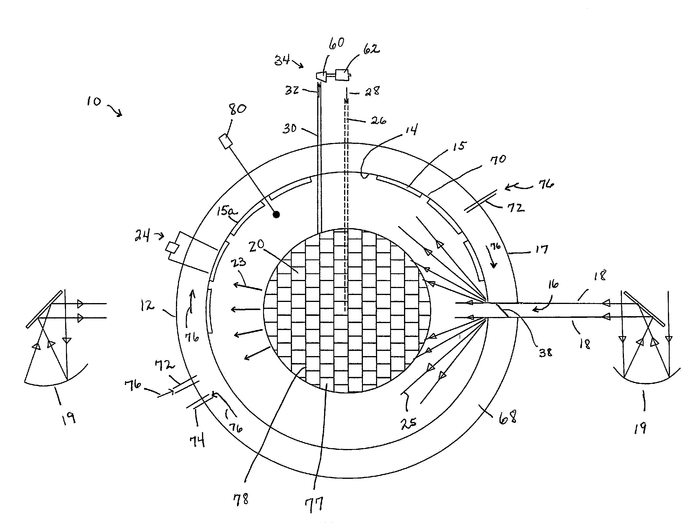
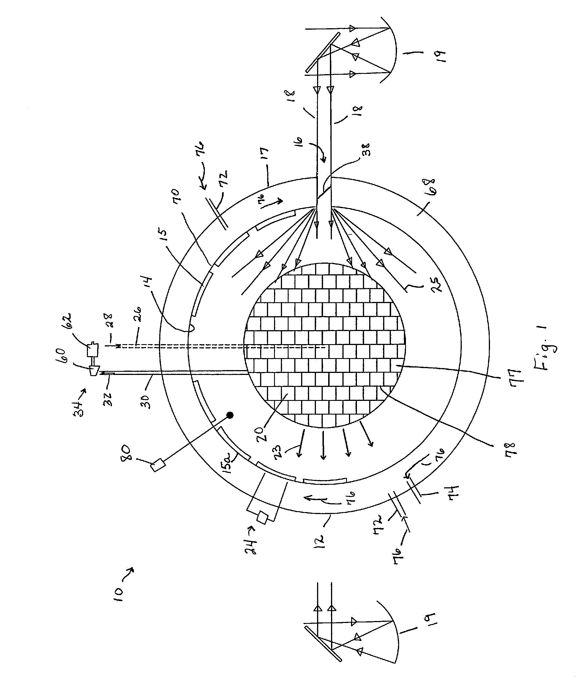
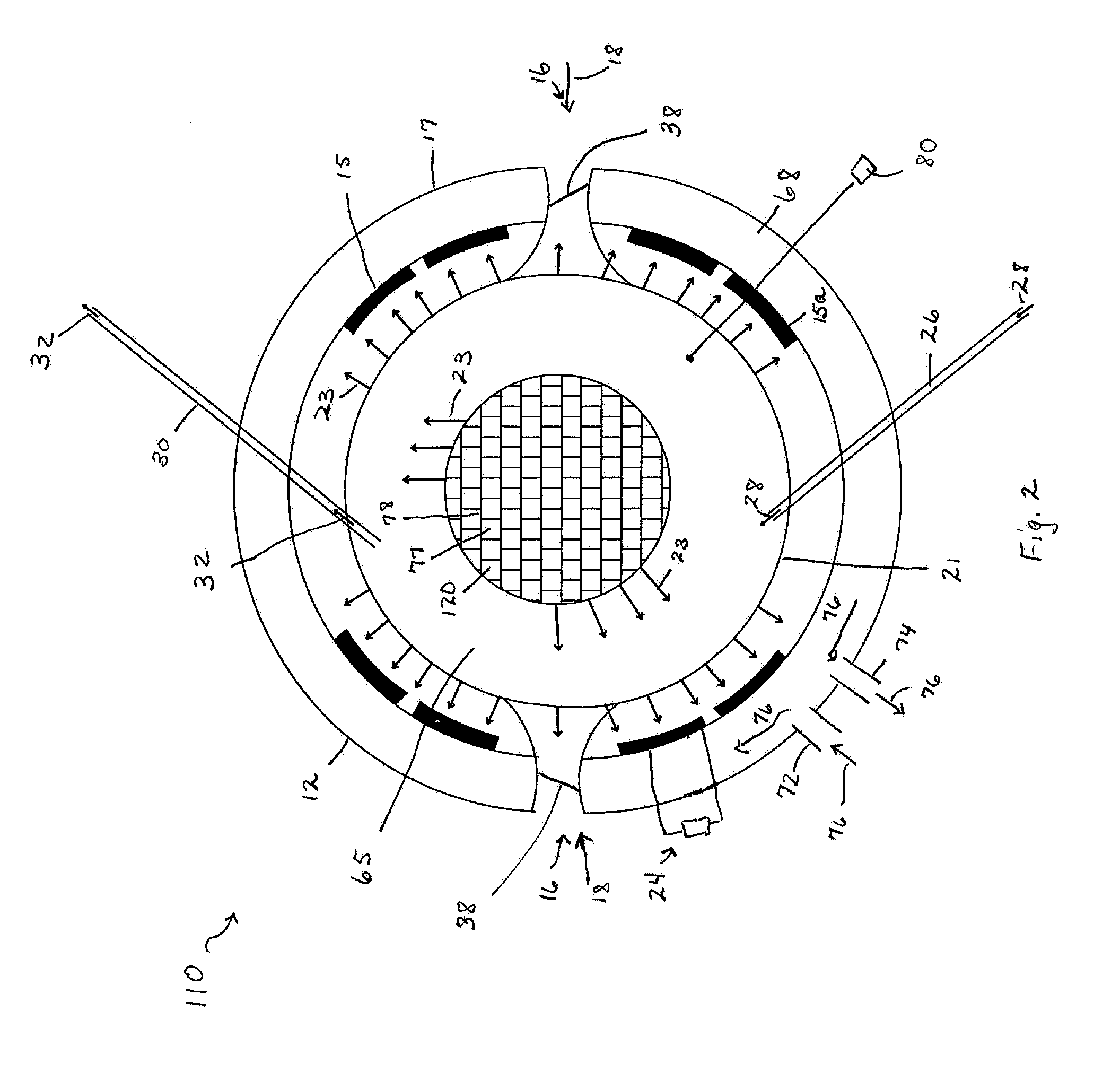
[0037]Reference is now made to FIGS. 1 and 2 which show schematic side elevation views of an apparatus, generally indicated as 10, 110, according to a first embodiment and a second embodiment, for converting solar energy into a mechanical and / or electrical en...


PUM


Abstract

A system for integrating and co-generating renewable energies which achieves a combined powerful AC/DC electricity output, includes an enclosed volume chamber having an inner surface including a plurality of thermophotovoltaic cells located thereon and an opening for admitting a condensed high-temperature solar energy beam. A heat absorbing member located within the chamber for receiving a portion of the solar energy beam and acts as a thermal storage as well as a thermal emitter to supply thermal energy to the thermophotovoltaic cells to create DC electricity. Air is fed into the chamber to capture thermal energy from the emitter and any waste thermal energy, which is then converted into AC electricity. The system relies on the power of simplicity using a new twist in solar physics to allow for the highest conversion of sunlight energy to electricity at zero carbon emission while occupying significantly less space than typical solar energy systems.

Description

CROSS-REFERENCE TO RELATED APPLICATION[0001]This application claims priority from U.S. Provisional Patent Application No. 61 / 998,754, filed Jul. 8, 2014, which is incorporated herein by reference.BACKGROUND OF THE INVENTION[0002]1. Field of the Invention[0003]The invention relates generally to an apparatus for converting solar energy into a usable energy product and, more particularly, to an economical system for converting a high percentage of sunlight radiant energy to electricity with negligible optical losses utilizing thermophotovoltaic cells. The system simultaneously produces both AC and DC electricity on a sustainable cycle with zero carbon emission.[0004]2. Description of Related Art[0005]Solar energy has been available as a source of power for more than 4.5 billion years. For centuries, inventors have been devising various means to harness this energy. As far back as the third century B.C., records indicate that the Greek and Roman armies used “burning mirrors” to focus su...

Claims


Application Information

Patent Timeline
Patent Type & Authority Applications(United States)
IPC IPC(8): H02S10/30F03G6/04
CPCF03G6/04H02S10/30F24S23/71F24S30/45F24S60/00F24S70/12F24S70/16H02S40/44Y02E10/46Y02E10/47Y02E10/50Y02E10/60Y02E10/40
Inventor TARABISHI, HISHAM
Owner TARABISHI HISHAM
Why Eureka
Try Eureka