Filter Element for Filtering Media

a filter element and filter media technology, applied in the direction of filter cartridge filters, filtration separation, separation processes, etc., can solve the problems of longer service life and increase in crude storage volume, and achieve the effect of high stability during operation and highest possible filter efficiency

Active Publication Date: 2016-01-21
MANN HUMMEL GMBH
View PDF3 Cites 5 Cited by
  • Summary
  • Abstract
  • Description
  • Claims
  • Application Information

AI Technical Summary

Benefits of technology

[0003]The object of the invention is to create a filter element that is stable, even at great pleat heights, and has the highest possible filter efficien

Problems solved by technology

Such an asymmetrical design results in an increase in the sto

Method used


Image

  • Filter Element for Filtering Media
  • Filter Element for Filtering Media
  • Filter Element for Filtering Media

Examples


Embodiment Construction

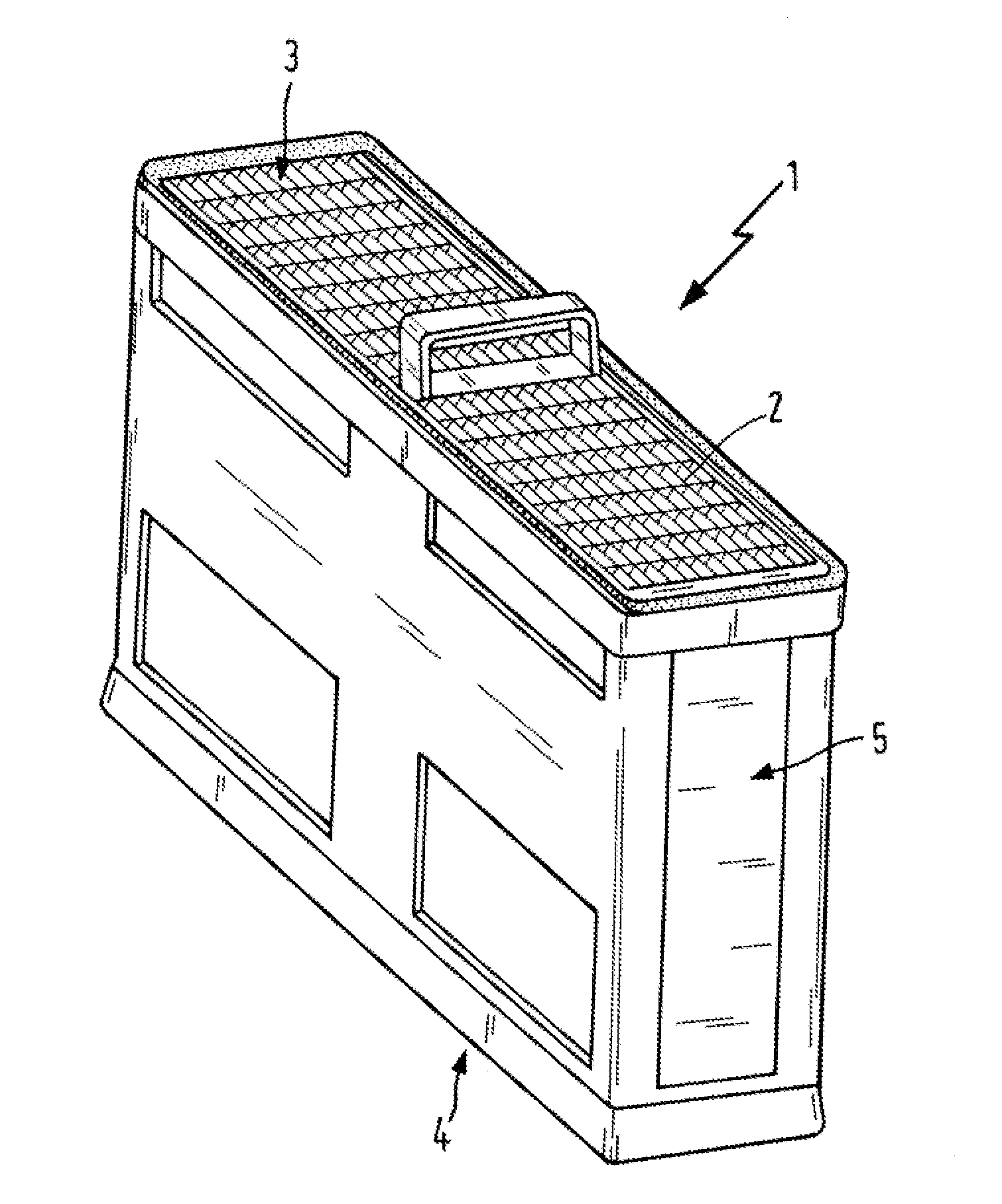
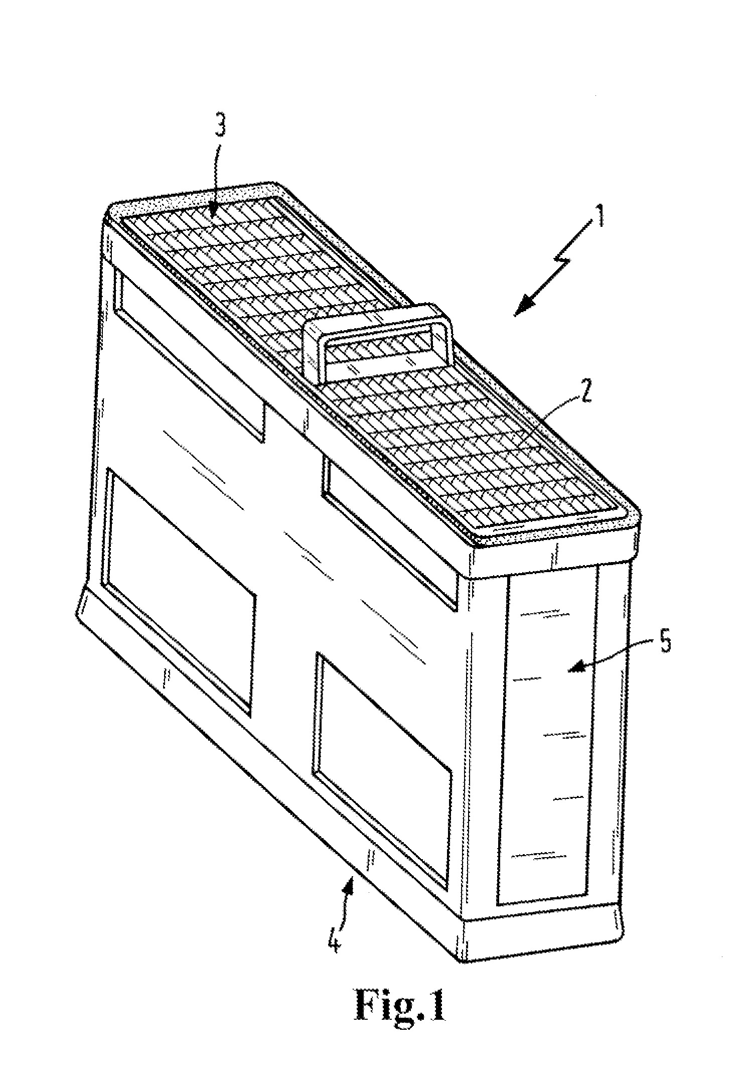
[0016]The filter element 1 shown in FIG. 1 has a filter bellows 2. The clean side outflow side 4 is on the opposite side. The filter bellows 2 are situated in a plastic housing 5.

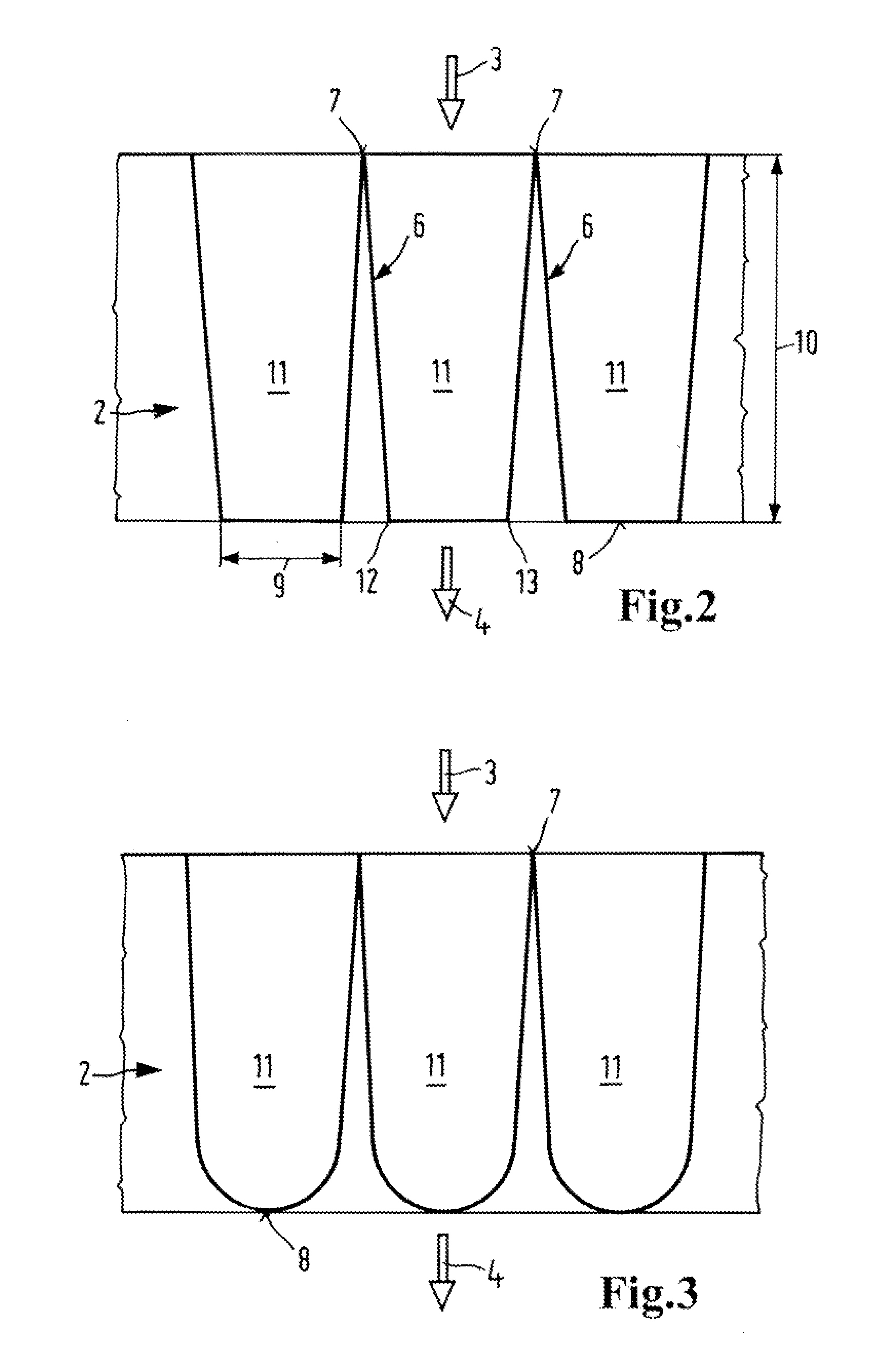
[0017]The filter bellows 2 shown in a detail in FIG. 2 and in a side view has pleated sheets 12, 13. The medium to be filtered approaches from the crude side 3 (oncoming flow side) and is removed on the clean side 4 (outgoing flow side). The pleat tip 7, which is exposed to oncoming flow, tapers to a tip. The base of the pleat 8 however is very wide. See the pleat spacing 9 in the region of the base of the pleat. Pleat pockets 11 of a substantial volume are formed in this way. Each pleat pocket is formed by two pleated sheets 12 and 13. The pleat height 10 is relatively great. In practice, a ratio of pleat height 10 to pleat spacing 9 on the order of 25:1 to 130:1 is the goal.

[0018]The pleat pockets 11 are essentially U-shaped. They are angular; see edges 6. They can be created by providing embossing lines....


PUM

PropertyMeasurementUnit
Lengthaaaaaaaaaa
Speedaaaaaaaaaa
Ratioaaaaaaaaaa

Abstract

A filter element for filtering media with a pleated filter medium is described. Each pleat (6) is formed by two pleated sheets which form a pleat tip (7) with one another on the crude side (3) exposed to oncoming flow. Two neighboring pleats (6) form a pleat base (8) with one another, wherein the crude side (3) and/or the clean side (4) of the filter medium has a plurality of elongated adhesive sections along at least two adhesive traces (14), each having at least one adhesive section and each having at least one adhesive interruption (15). The mutual spacing of the two pleated sheets in the region of the pleat tip (7) is between zero and two mm or the two pleated sheets are in contact with one another in the region of the pleat tip (7), wherein the pleat spacing (9) between the two pleated sheets of a pleat pocket (11) amounts to at least twice the pleat spacing in the region of the pleat tip 7 in the region of the pleat base (8).

Description

TECHNICAL FIELD[0001]The invention relates to a filter element for a filter for filtering media, in particular gases, in particular intake air, fuel or motor oil, in particular in an internal combustion engine, in particular in a motor vehicle, or ambient air for introduction into ventilation systems in buildings or motor vehicles, having a pleated filter medium with a crude side and a clean side, wherein numerous elongated adhesive sections are arranged along at least two traces of adhesive on the crude side and / or on the clean side of the filter medium, wherein at least one adhesive section and at least one adhesive interruption are arranged on each adhesive trace. The adhesive traces serve in particular to stabilize the filter element and / or to stabilize the pleats.BACKGROUND[0002]Various filters having pleated filter media are known from the prior art. WO 2007 / 056567 A1 describes a device and a method for producing pleated filter elements of different pleat heights. WO 2011 / 0269...

Claims


Application Information

Patent Timeline
IPC IPC(8): B01D29/03B01D46/52
CPCB01D46/522B01D29/031B01D46/10
Inventor MOUANDA, GELASE MBADINGAHEIM, MICHAELKLEIN, GUNNAR-MARCEL
Owner MANN HUMMEL GMBH
Why Eureka
Try Eureka