


Quick Research
Generate reliable direction feasibility study reports for your R&D in just a few steps.

Technical Q&A
Discover and master advanced knowledge NOW. Basics, ideas, possibilities, all at once.

Find Solutions
As an expert in R&D theories, this can generate solutions to your technical problems instantly.

Evaluate Feasibility
Analyze your overall solution with one click, know your potential R&D risks in advance.

Monitor Landscape
Get weekly tech updates, stay abreast of the latest tech innovations and key insights.
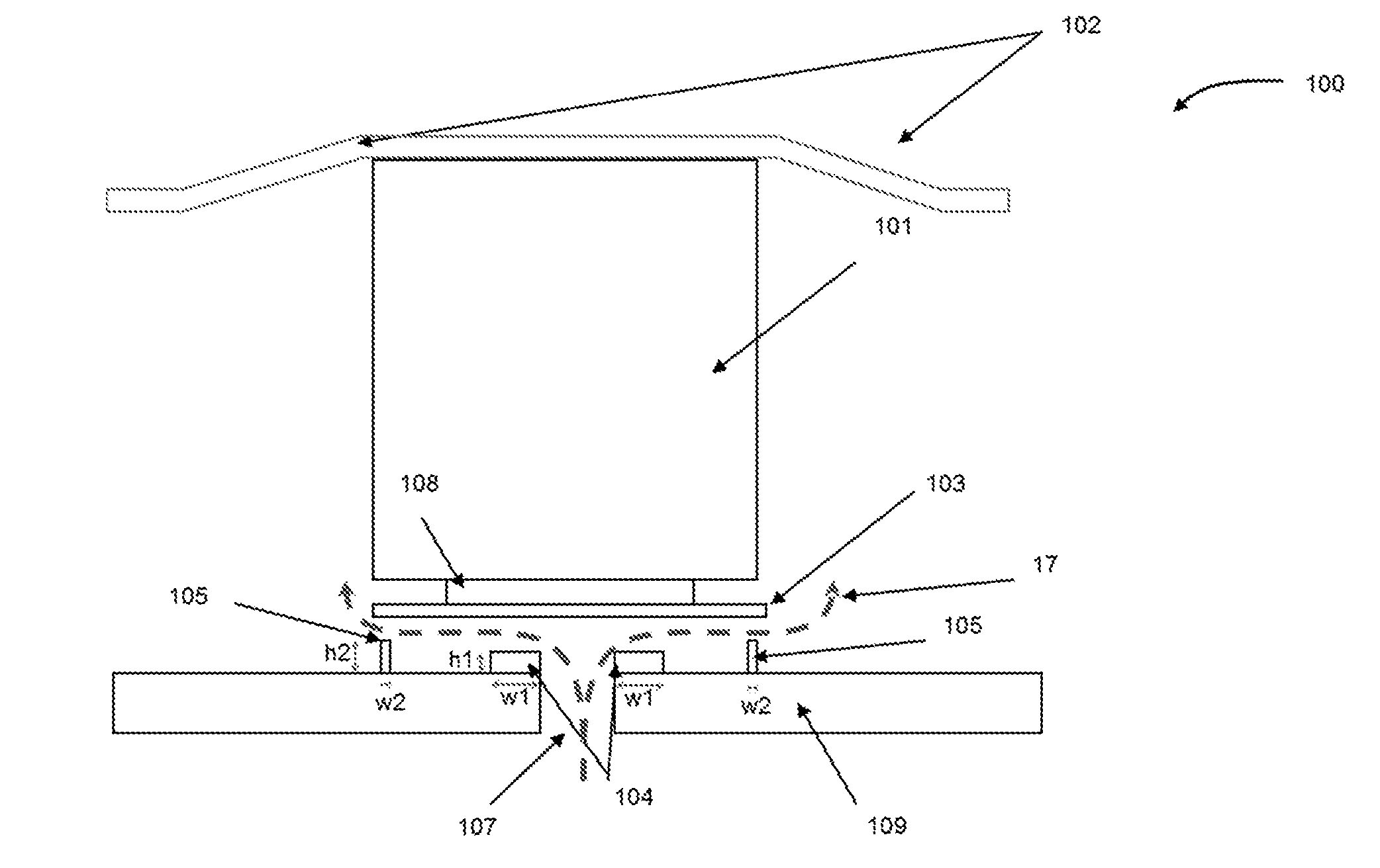
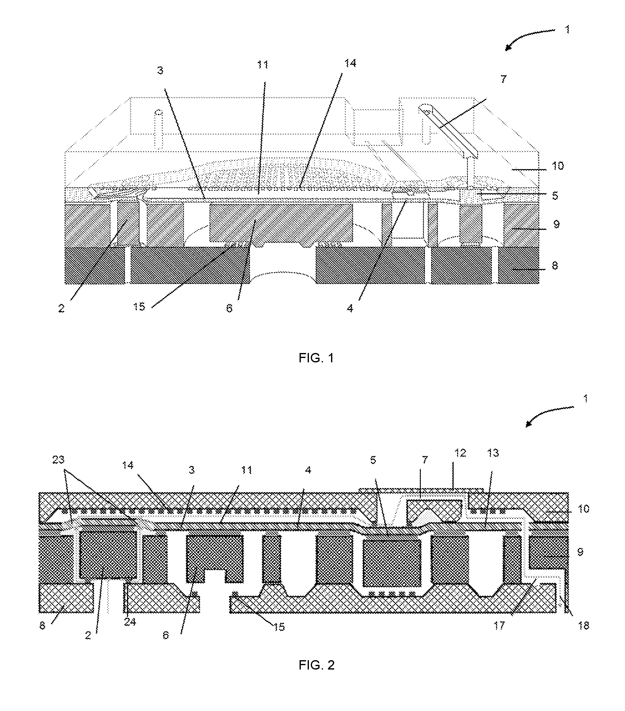
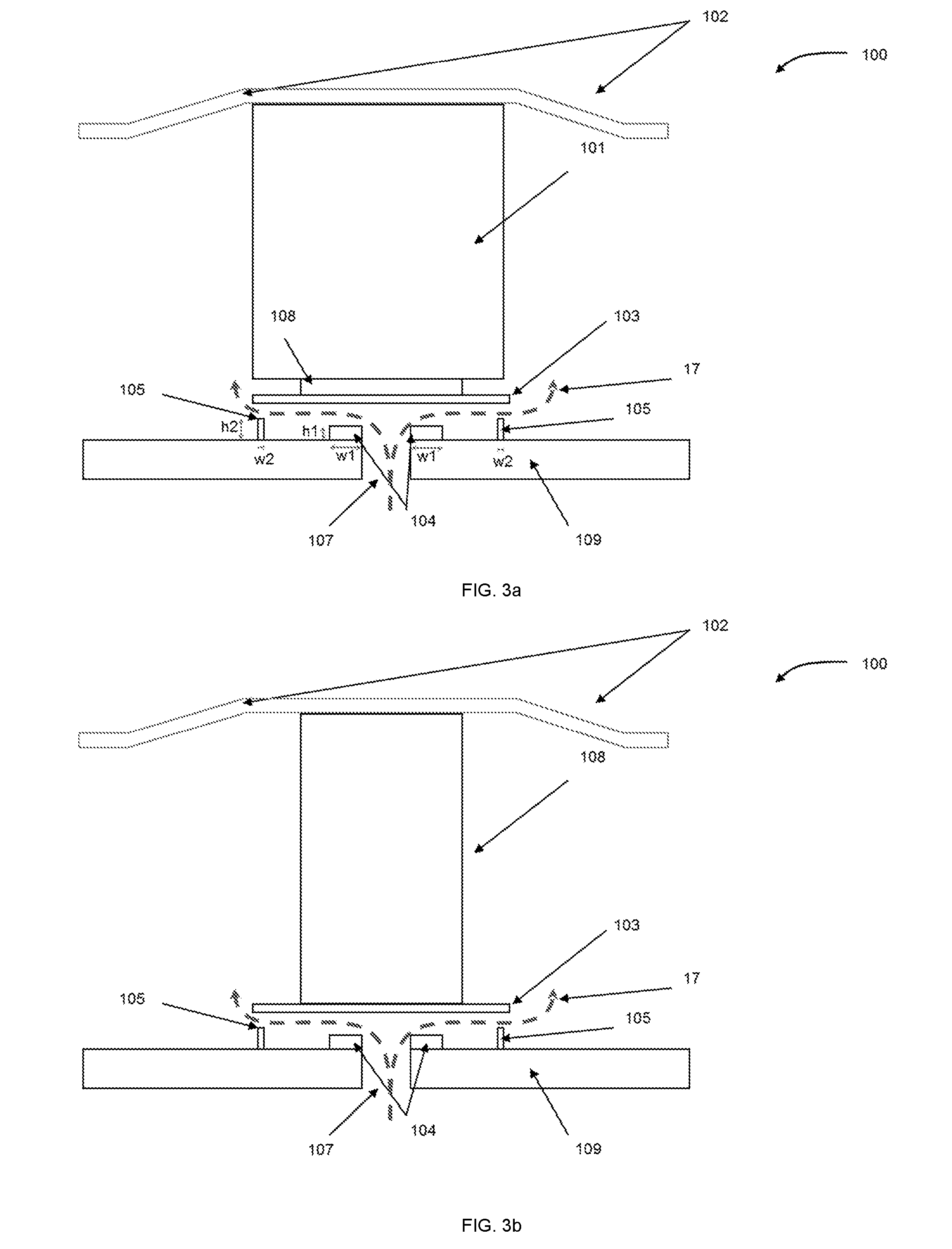
Microfluidic valve having improved tolerance to particles
a microfluidic valve and particle technology, applied in the field of valves, can solve the problems of no one being able to ensure the tightness, risk of pump backflow, free flow, etc., and achieve the effect of reducing the potential value of backflow, increasing the probability and very low risk of catching a particl
- Summary
- Abstract
- Description
- Claims
- Application Information
AI Technical Summary
Benefits of technology
Problems solved by technology
Method used
Image

Examples
Embodiment Construction
[0078]In the following detailed description, reference is made to the accompanying drawings that form a part hereof, and in which are shown by way of illustration several embodiments of devices, systems and methods. It is to be understood that other embodiments are contemplated and may be made without departing from the scope or spirit of the present disclosure. The following detailed description, therefore, is not to be taken in a limiting sense.
[0079]As used in this specification and the appended claims, the term “or” is generally employed in its sense including “and / or” unless the content clearly dictates otherwise.
[0080]As used in this specification and the appended claims, any direction referred to herein, such as “top”, “bottom”, “left”, “right”, “upper”, “lower”, and other directions or orientations are described herein for clarity in reference to the figures and are not intended to be limiting of an actual device or system. Devices and systems described herein may be used in...
PUM
 Abstract
Description
Claims
Application Information
 - R&D Engineer
- R&D Manager
- IP Professional
- Industry Leading Data Capabilities
- Powerful AI technology
- Patent DNA Extraction
Browse by: Latest US Patents, China's latest patents, Technical Efficacy Thesaurus, Application Domain, Technology Topic, Popular Technical Reports.
© 2024 PatSnap. All rights reserved.Legal|Privacy policy|Modern Slavery Act Transparency Statement|Sitemap|About US| Contact US: help@patsnap.com