Connecting device for light fixtures

a technology of connecting device and light fixture, which is applied in the field of light fixture, can solve the problems of low luminous efficiency of light fixture, inconvenient mounting and dismounting, etc., and achieve the effects of maximum luminous efficiency, and convenient mounting and dismounting

Active Publication Date: 2016-01-21
WAC LIGHTING DONGGUAN +1
View PDF10 Cites 12 Cited by
  • Summary
  • Abstract
  • Description
  • Claims
  • Application Information

AI Technical Summary

Benefits of technology

[0013]The present invention has the following beneficial effects. 1. The connecting device for light fixtures provided by the present invention is convenient in mounting and dismounting. When the lens fixing plate and the light fixture assembly connected to each other, the lens fixing plate is put into the light fixture assembly, and the connecting rod is pushed to be fixedly connected to the buckle once the button on the lens fixing plate is pressed down by a hand. While the connecting rod is clamped by the buckle, the lens fixing plate is pushed under the action of the first spring to enable the lens mounted on the lens fixing plate to be in good and gapless fit with the LED light source mounted on the LED light source mounting plate of the light fixture assembly, thereby enabling the light fixtures to achieve maximum luminous efficiency. When the lens fixing plate is to be dismounted from the light fixture assembly, the connecting rod is pushed by the button and then retracted from the buckle so long as the button on the lens fixing plate is pressed down by a hand, that is, the lens fixing plate is dismounted. From the above description, it is concluded that such a connecting device for light fixtures is quite convenient in mounting a

Problems solved by technology

In square LED track light fixtures in the prior art, a lens fixing plate and a light fixture assembly are connected to each other, generally fixedly connected by screws or by elastic sheets sometimes. Connecting the lens fixing plate with the light fixture assembly by screws or elastic sheets causes inconvenience in mounting and dismounting.
As a result, the lens fixing plate and the light fixture assembly must be mounted or dis

Method used


Image

  • Connecting device for light fixtures
  • Connecting device for light fixtures
  • Connecting device for light fixtures

Examples


Embodiment Construction

[0023]The present invention will be further described as below in details with reference to the accompanying drawings and specific embodiments. However, the scope of implementation of the present invention is not limited thereto.

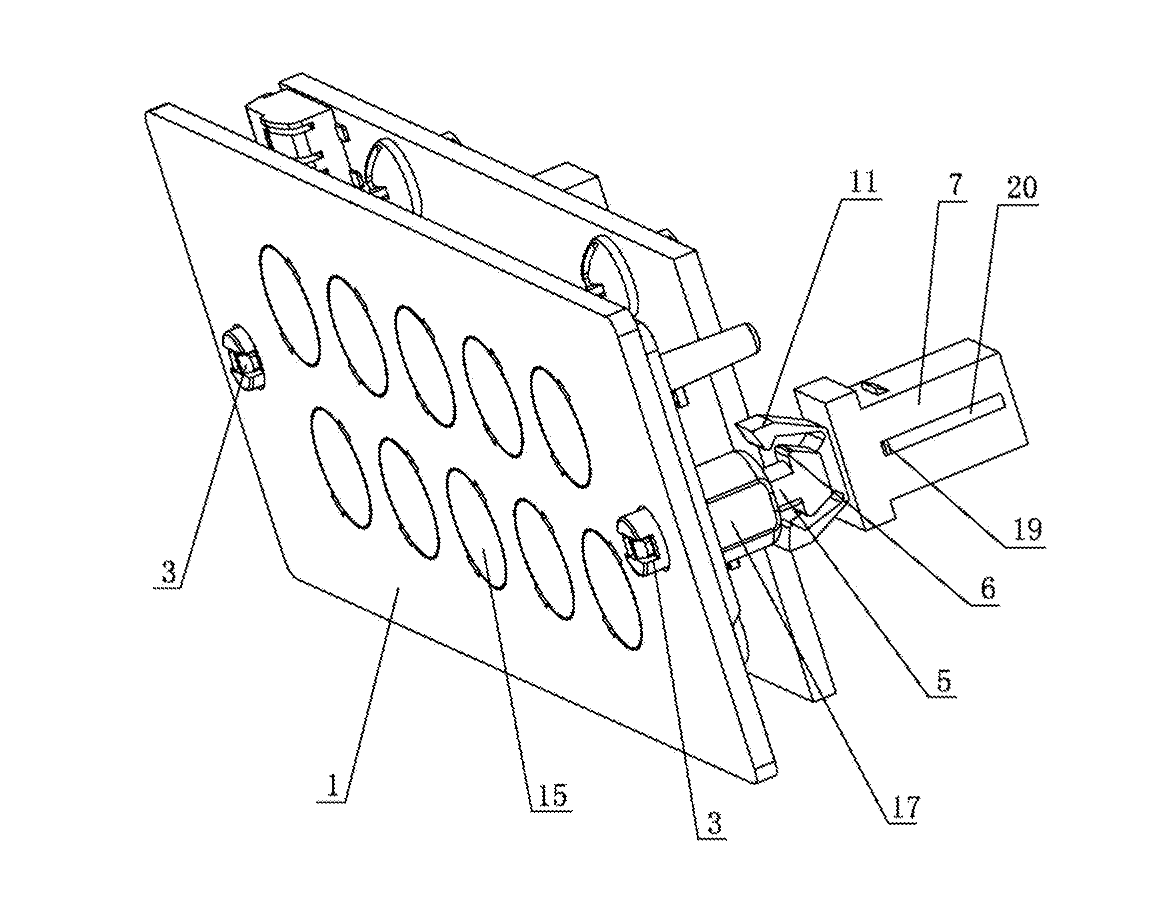
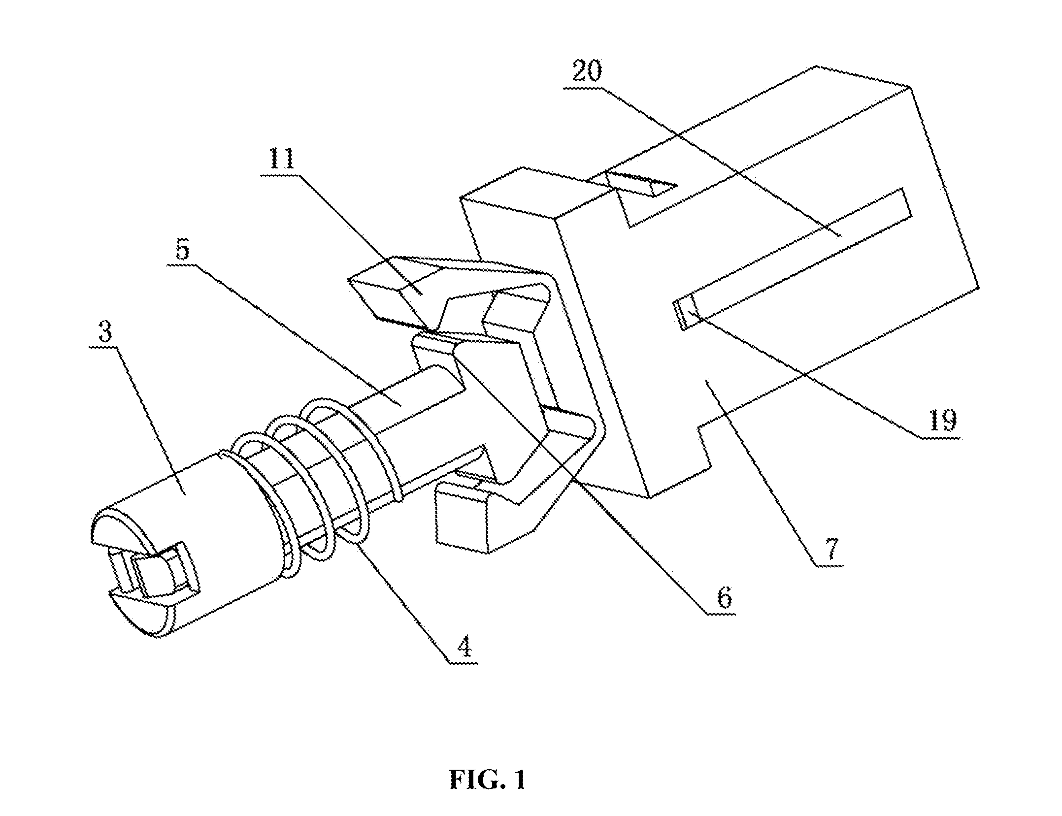
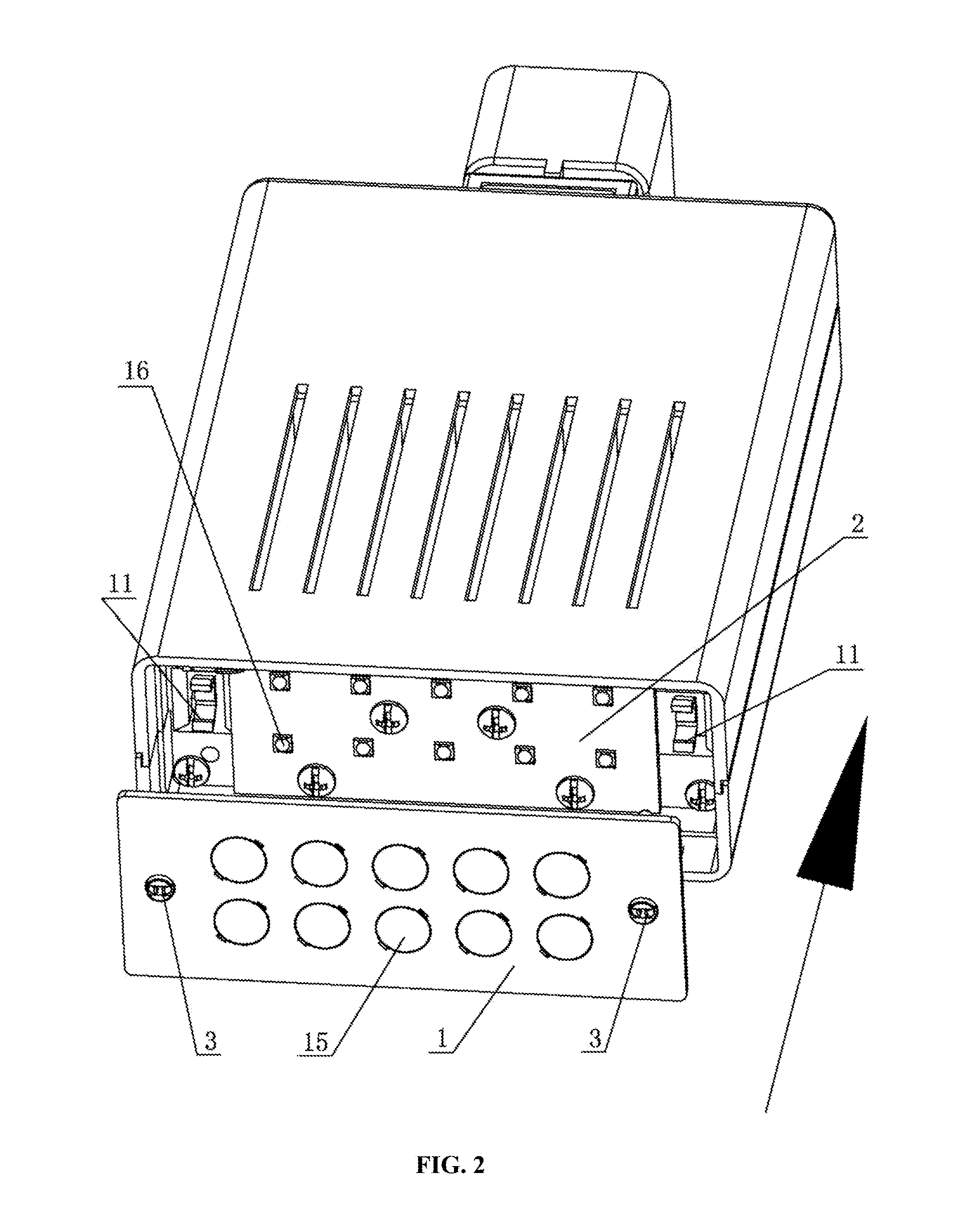
[0024]As shown in FIGS. 1-4, a connecting device for light fixtures according to an embodiment of the present invention is provided, including a lens fixing plate 1 and a light fixture assembly 2. Multiple lenses 15 are mounted on the lens fixing plate 1, and multiple LED light sources 16 are mounted on an LED light source mounting plate of the light fixture assembly 2. When the lens fixing plate 1 is connected to the light fixture assembly 2, the lenses 15 and the LED light sources 16 are arranged correspondingly one by one. The connecting device for light fixtures further includes a button 3, a first spring 4, a connecting rod 5 and a buckle. The buckle is fixedly connected to the light fixture assembly 2. A mounting base 17 is disposed on the lens fixing ...


PUM


Abstract

A connecting device for light fixtures has a lens fixing plate, a light fixture assembly, a button, a first spring, a connecting rod and a buckle. The buckle is fixedly connected to the light fixture assembly. A mounting base is disposed on the lens fixing plate. One end of the connecting rod is located in an inner cavity of the mounting base and the other end thereof is extended out from the mounting base. The end of the connecting rod extending out from the mounting base is provided with a boss, and the connecting rod located in the inner cavity of the mounting base is sleeved with the first spring. The button is connected to the end of the connecting rod located in the inner cavity of the mounting base.

Description

FIELD OF THE INVENTION[0001]The invention relates to the technical field of light fixtures, and particularly to a connecting device for light fixtures.BACKGROUND OF THE INVENTION[0002]In square LED track light fixtures in the prior art, a lens fixing plate and a light fixture assembly are connected to each other, generally fixedly connected by screws or by elastic sheets sometimes. Connecting the lens fixing plate with the light fixture assembly by screws or elastic sheets causes inconvenience in mounting and dismounting. As a result, the lens fixing plate and the light fixture assembly must be mounted or dismounted by tools or by a large force. Connecting the lens fixing plate with the light fixture assembly by screws or elastic sheets cannot play a role of light compensation to the light fixtures, that is, a lens mounted on the lens fixing plate cannot be in close contact with an LED light source mounted on an LED light source mounting plate of the light fixture assembly, resultin...

Claims


Application Information

Patent Timeline
IPC IPC(8): F21V17/16F21V17/06
CPCF21V17/06F21V17/164F21V5/007F21V5/04F21V17/10F21Y2101/00F21Y2105/10F21Y2115/10F21V17/16F21V21/00F21V23/06
Inventor GUO, ROGERHU, JAYBASAR, ERDENER
Owner WAC LIGHTING DONGGUAN
Why Eureka
Try Eureka