Single-source precursor for semiconductor nanocrystals

a semiconductor nanocrystal and single-source technology, applied in the direction of conductors, cellulosic plastic layered products, other chemical processes, etc., can solve the problems of toxic nature of surface capping agents such as mercaptoacetic acid, mercaptoethanol, etc., to achieve high luminescence efficiency, facilitate efficient, and increase luminescence quantum efficiency

Active Publication Date: 2012-10-16
DIRECTOR GENERAL DEFENCE RES & DEV ORG
View PDF8 Cites 0 Cited by
  • Summary
  • Abstract
  • Description
  • Claims
  • Application Information

AI Technical Summary

Benefits of technology

[0052]Another advantage of the present invention is that the nanoparticles formed are not freely-flowing particles, instead they are embedded within the partially or fully decomposed layered compound [18] as shown in FIG. 4. Magnified region of a large thin platy crystallite of a partially decomposed product shows that ZnS nanoparticles of ˜5 nm size [19] are embedded within the micro-crystallites. The selected area ED pattern [20] also shows the presence of sphalerite nanoparticles and the mixed XRD reflections [21] from the layered precursor (LP), ZnS (cubic) nanoparticles and the ZnO micro-shell confirm the unique composite feature. This architecture ensures that the nanoparticles will not diffuse and contaminate the environment. Thus the invention provides a novel way of making environmentally safe but functionally potential nanoparticles.
[0053]Still another advantage of the present invention is that the functionalized nanoparticles embedded within the layered compound is in situ surface-capped with a transparent (UV-VIS) semiconductor oxide of ZnO. When the precursor is decomposed in aqueous medium under air environment, the ZnS nanoparticles are preferably formed by the predominant reaction of the gallery occupants (Thio-derivative / S2-source) with its ‘corbel’ containing Zn2+ ions at the octahedral / tetrahedral sites. Subsequently on heat treatment the ZnO shells are formed and grow into sub-micrometer thicknesses due to the decomposition of the ‘corbel’ of the layered precursor. The material shows maximum luminescence efficiency with the formation of ZnO shells. In the XRD pattern (FIG. 3 [21]) of efficiently luminescent samples, the presence of the sharp ZnO reflections as against the broadened cubic-ZnS nanoparticle pattern, which remains unchanged in line width, clearly indicate the deduced mechanism. The ZnO caps effectively passivate the defect-related non-radiative pathways at the nanoparticle surface and thereby increase the luminescence quantum efficiency.
[0054]A further advantage of the present invention is that, the emission color of the nanoparticles can be effectively tuned over a wide range from blue (˜480 nm) to red (˜618 nm) by a single step process of controlled decomposition of the initial precursor. The emission color is modified by way of changing the phase content of nano-ZnS / micro-ZnO shell. The compositional changes are evident from the XRD pattern in FIG. 3. With partial surface oxidation of ZnS nanoparticles or incorporation of oxygen in nano sized ZnS surface, and also the formation of oxygen-deficient ZnO1-δ at the surface with Cu+ and Al3+ at Zn2+ site, leads to changes in the PL emission characteristics from green to yellow, orange or red. Oxygen vacancies (Vo) in ZnO act as donor centers and gives green PL emission whereas the interstitial oxygen gives rise to orange-red emission. The δ value in ZnO1-δ decreases with the extent of oxidation (heat treatment) and accordingly, the concentration of oxygen vacancies decreases whereas the interstitial oxygen increases leading to red-shift in emission colors as seen in the photoluminescence spectra [22] (FIG. 5). Thus the emission color is tuned by changing the nano-ZnS / micro-ZnO core / shell ratio at the interface.
[0055]Yet another important advantage of the present invention is that the decomposition of the layered precursor leads to specific type of microstructure wherein the doped nanoparticles embedded have a lossy-dielectric behavior at ac electric-field. This facilitates efficient, low-voltage, ac electroluminescence (EL) from the doped ZnS nanocrystals. FIG. 6 refers to the EL emission spectra [23] from ac-powder-EL (ACPEL) cells made by using two different kind of doped nanoparticles systems (decomposed products) of the present invention. EL activity can be seen only in materials containing predominantly ZnS nanoparticles rather than ZnO particles, which is not EL active. Efficient blue-green and green-yellow EL emission can be obtained from Cu—Al doped nano ZnS+micro ZnO particles whereas the orange emission (590) is obtained from ZnS:Cu+—Mn2+-Al3+, as described in example 4. Thus, the new, environment-friendly nanoparticles can be used for multi-color emitting EL displays, CRT displays, field emission displays, projection screens, etc.
[0056]Yet another advantage of the present invention is that the nanophosphors prepared by the present invention does not contain any toxic or carcinogenic elements, unlike the case of CdSe, CdS or ZnSe based luminophors. Therefore, these particles are safe for both in vitro as well as in vivo biological applications such as bio-labeling and medical imaging. Further, bio-molecules of pharmaceutical importance (drugs) can be intercalated into the gallery space of the layered structure and the composite may be used as a new drug-delivery system wherein the luminescence from the nanoparticles can be used to activate or monitor the drug delivery mechanism in biological tissues.
[0057]The present invention is illustrated with the help of the following examples, which are not intended to limit the scope of the invention and any modifications falls within the scope of this invention.

Problems solved by technology

Though the method was widely used in the early stages for making intrinsic II-VI group nanoparticles, but it was found not suitable for making doped nanoparticles because of the unavoidable use of excess surfactant medium which hinder the doping process.
The excess surfactant also causes difficulties in the separation of nanoparticles from the reaction medium for any technological applications.
Yet another disadvantage of this process is that the surface capping agents used such as mercaptoacetic acid, mercaptoethanol, etc (thiol compounds, in general) are toxic in nature.
The process also suffer from low-yield of the precipitate.
However, this method has only limited acceptability because of the use of costiler and often poisonous organometallic chemicals.
Moreover, these chemicals are rarely available or have to be freshly prepared in-house through highly controlled and stringent chemical reactions (U.S. Pat. No. 5,525,377).
This results in the high cost of the products (Approx.
Another disadvantage of this method is the use of toxic hydrogen sulfide (H2S) gas (in case of sulfide nanocrystals) as the source of S2-ions.
A further disadvantage of this process is that the organometallic precursors of dopants such as Mn2+, (diethyl manganese) are highly unstable and either polymerize or precipitate as separate phase during the co-precipitation reactions.
Yet another disadvantage of this method is that the known art does not provide a common reaction route for the incorporation of multiple dopant ions in the semiconductor lattice, which is necessarily required for multicolor-emission from the nanophosphors.
The process is also time consuming as the dissolution of the surfactants or capping polymer (e.g. PMMA) in organic solvent (toluene) takes about 12-18 hours.
Although these methods are adequate for the preparation of nanosized particles, however, they do not represent a convenient and generalized methodology for doping of different impurity ions having various valence states.
The methods also suffer from the disadvantage of immediate surface oxidation of nanoparticles which invites the requirement of inert atmosphere for the preparation.
A major disadvantage for the nanoparticles systems prepared by all the aforesaid known processes is that they are highly dispersible in air and water and therefore cause potential environmental threats.
These findings reveal the main limitation of presently available luminescent nanoparticles.
Thus, the existing methods and materials related to luminescent nanoparticles are attended with disadvantages and drawbacks described hereinabove.

Method used


Image

  • Single-source precursor for semiconductor nanocrystals
  • Single-source precursor for semiconductor nanocrystals
  • Single-source precursor for semiconductor nanocrystals

Examples


example 1

Synthesis of Green Emitting Nanocrystals in Aqueous Medium

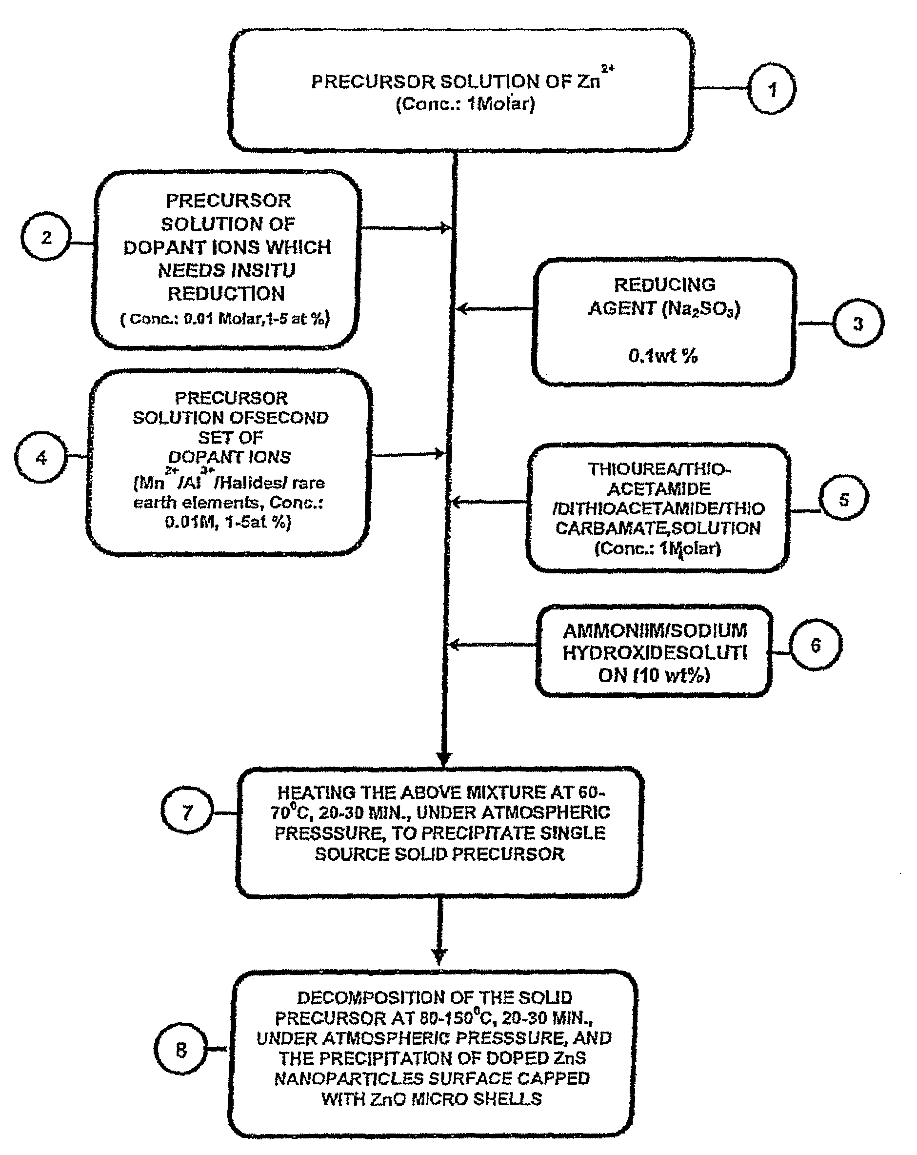
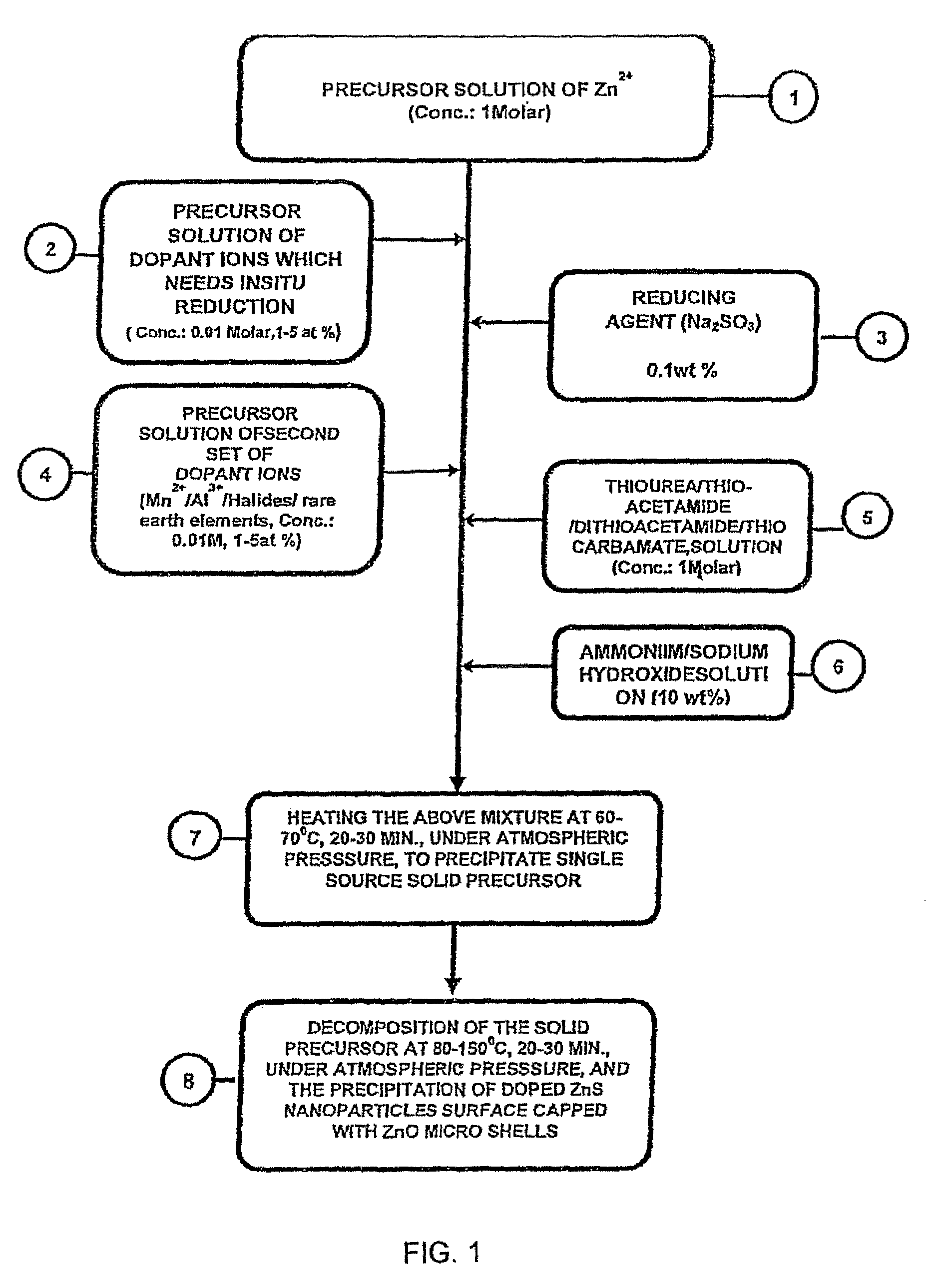
[0058]For the preparation of nanocrystals, 500 ml of IM zinc sulfate aqueous solution is mixed homogenously with 50 ml of 0.01M copper acetate (1 at % Cu2+) solution and 10.0 mg of anhydrous Sodium Sulphite Powder. The mixture thus obtained is added with 100 ml of 0.01 M aluminum nitrate solution (2 at % Al3+) and 500 ml of I M thiourea. In the next step NH4OH solution is added until the pH of the reaction mixture raises to 10-11, which is heated to 60-70° C. for a period of 20-30 minutes to obtain a white precipitate which is filtered and subsequently washed and dried at 50-60° C. for its storage. Alternatively, the precipitate is decomposed in the mother-liquor by increasing the temperature to 100-110° C. for a period of 15-17 minutes. Further, alternatively, Teflon-lined reactor (autoclave) may also be used for the heat treatment of the precipitate at a temperature of 100-110° C. The precipitate thus treated is subjected t...

example 2

Synthesis of Yellow Emitting Nanocrystals in Aqueous Medium

[0059]For the preparation of nanocrystals, 500 ml of IM zinc sulfate aqueous solution is mixed homogenously with 50 ml of 0.01 copper acetate (1 at % Cu2+) solution and 10.0 mg of anhydrous Sodium Sulphate Powder. The mixture thus obtained is added with 100 ml of 0.01 M aluminum nitrate solution (2 at % Al3+) and 500 ml of I M thiourea. In the next step NH4OH solution is added until the pH of the reaction mixture raises to 10-11, which is heated to 60-70° C. for a period of 20-30 minutes to obtain a white precipitate. This solid-precursor is either separated and stored for use or decomposed by increasing the temperature of reaction medium to 110-130° C. for a period of 15-17 minutes to obtain precipitate containing the doped nanocrystals Further, alternatively, Teflon-lined reactor (autoclave) may also be used for the heat treatment of the precipitate at a temperature of 110-130° C., which is filtered, washed and dried of 70...

example 3

Synthesis of Orange Emitting Nanocrystals in Aqueous Medium

[0060]For the preparation of nanocrystals, 500 ml of 1M zinc sulfate aqueous solution is mixed homogenously with 50 ml of 0.01M copper acetate (1 at % Cu2+) solution, and 10.0 mg of anhydrous sodium sulphite powder. The mixture thus obtained is added with 100 ml of 0.01M aluminum nitrate solution (2 at % Al3+), 50 ml of 0.001M manganese sulphite (MnSO4 n H2O) and 500 ml of 1M thiourea. In the next step, 5% solution of NH4OH or NaOH solution is added until the pH of the reaction mixture raises to ˜9, which is heated to ˜60-70° C. for a period of 20-30 minutes, under atmospheric pressure, to obtain a white precipitate which is decomposed in air or water at 130-140° C. to generate Cu+—Mn2+—Al3+ doped ZnS nanoparticles covered with ZnO shell. The precipitate thus obtained is filtered, washed and dried at 70-80° C. The nanocrystals thus obtained shows bright orange luminescence at 590 nm, the yield of which is ˜90% and the same i...


PUM

PropertyMeasurementUnit
temperatureaaaaaaaaaa
boiling pointaaaaaaaaaa

Abstract

A process for preparing a single source solid precursor matrix for semiconductor nanocrystals having the steps of: mixing 0.1-1 Molar of an aqueous/non-aqueous (organic) solution containing the first component of the host matrix with 0.001-0.01 Molar of an aqueous/non-aqueous solution containing the first dopant ions, which needs in situ modification of valency state, dissolving 10-20 milligram of an inorganic salt for the in situ reduction of the first dopant ion in the solution, addition of 0.001-0.01 Molar of an aqueous/non-aqueous solution of an inorganic salt containing the dopant ions which do not need modifications of their valency state, addition of 0.1-1 Molar of an aqueous/non-aqueous solution of an inorganic salt containing the second component of the host material, addition of 5-10% by weight of an aqueous solution containing a pH modifying complexing agent, to obtain a mixture, and heating the mixture to obtain a solid layered micro-structural precursor compound.

Description

BACKGROUND OF THE INVENTION[0001]A single source solid precursor matrix for producing semiconductor nanocrystals and doped semiconductor nanocrystals for displays / bio-labels and a process for preparation thereofFIELD OF INVENTION[0002]This invention is related to a single source solid precursor matrix for producing semiconductor nanocrystals and doped semiconductor nano crystals for displays and a process for preparation thereof. The doped semiconductor nanocrystals of II-VI compounds generated in situ within an inorganic layered precursor (LP) and particularly doped ZnS nanocrystals surface capped with ZnO micro-shell, both generated and remain embedded within the decomposed zinc-thiourea-sulfato-hydroxide precursor matrix. The composite material shows efficient photo- and electro-luminescence suitable for making multicolor displays and bio-markers.PRIOR ART[0003]The luminescent semiconductor nanocrystals, generally termed as nanophosphors, are employed as the materials for display...

Claims


Application Information

Patent Timeline
Patent Type & Authority Patents(United States)
IPC IPC(8): B05D7/00
CPCC09K11/642C30B7/00C30B29/16C30B29/605H01L33/285C30B29/48Y10T428/2991
Inventor KOYAKUTTY, MANZOORVERMA, ADITYAVEDERA, SAMPAT RAJKUMAR, NARENDRAKUTTY, THUNDYIL RAMAN NARAYANA
Owner DIRECTOR GENERAL DEFENCE RES & DEV ORG
Why Eureka
Try Eureka