
Terminal Box and Method of Connecting Output Line

a terminal box and output line technology, applied in the direction of electrical cable installation, electrical apparatus construction details, connections, etc., can solve the problems of operator forgetting to create such play, contact failure still might occur, contact failure, etc., to ensure the play is surely provided, easy and surely provide a certain length of output line, stable and stable quality of the terminal box

Active Publication Date: 2016-01-21
HOSIDEN CORP
View PDF13 Cites 4 Cited by
  • Summary
  • Abstract
  • Description
  • Claims
  • Application Information

AI Technical Summary

Benefits of technology

The terminal strip in this patent includes a connecting portion and a play producing portion. The play producing portion inclines at an angle relative to the connecting portion to connect and fix the output line. The play producing portion is then moved to a smaller angle, allowing for easy and sure play in the output line. This arrangement ensures good quality and stability when attached to a solar cell module, and the operator can visually confirm the play is provided. The terminal strip also allows for easy adjustment of the angle without straining or distorting it, providing flexibility in creating play in the output line.

Problems solved by technology

With the terminal box disclosed in Japanese Patent No. 4,384,241, for example, the output lead might crack or peel off at the soldered connection by shrinkage or expansion if the output lead is connected to the terminal base with no play, which results in contact failure.
In that case, however, the operator may forget to create such play in the output line or may produce variations in creating the play.
Thus, the contact failure still might occur if the operator connects the output line to the terminal strip without creating the play or with shortage of play.
In this time, the output line is bent in contact with one of the four sides of the opening that is closest to the connecting portion and thus might be damaged or marred if the side contacting the output line creates a sharp edge.

Method used


Image

  • Terminal Box and Method of Connecting Output Line
  • Terminal Box and Method of Connecting Output Line
  • Terminal Box and Method of Connecting Output Line

Examples


Embodiment Construction

1. Overall Construction of Terminal Box

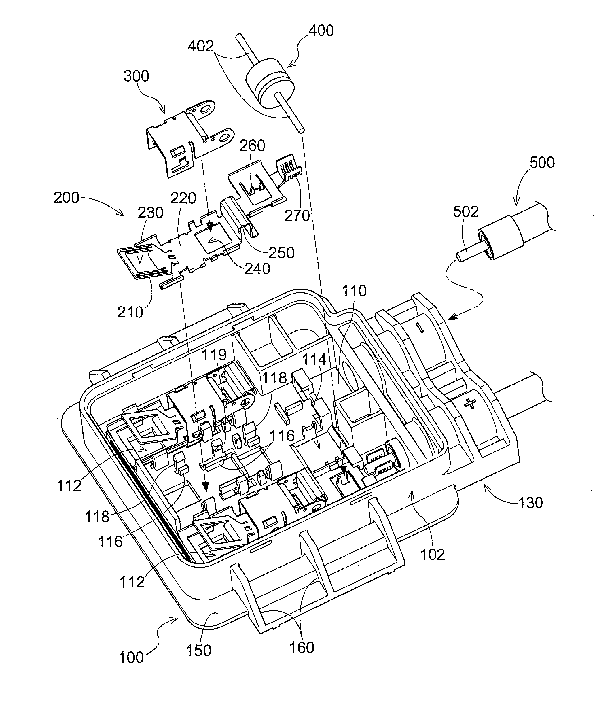
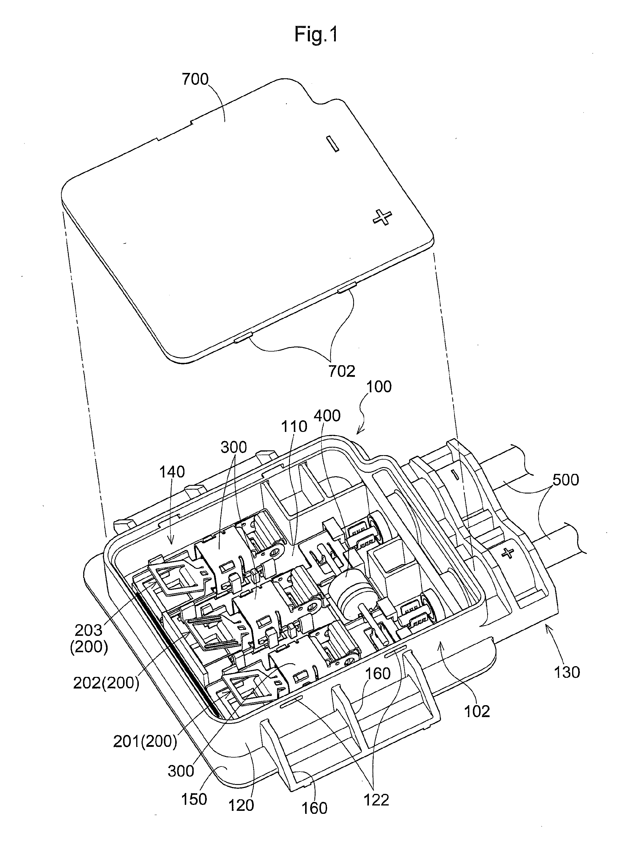
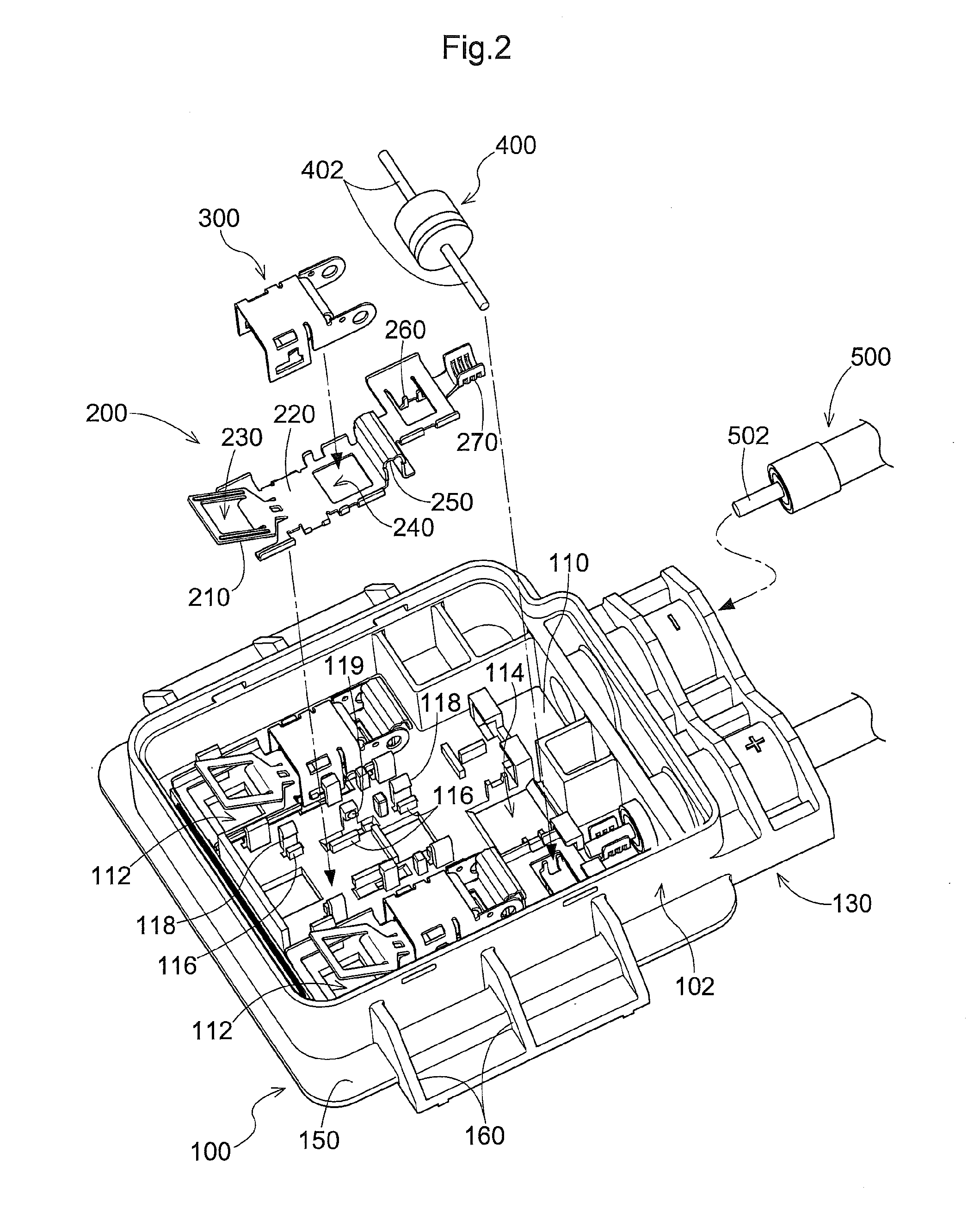
[0026]Embodiments of a terminal box relating to this disclosure will be described in detail in reference to the accompanying drawings. Referring to FIG. 1, the terminal box includes a main body 100, a lid 700, three terminal strips 200 provided inside of the main body 100, three connecting elements 300, a diode 400, and output cables 500. The main body 100 and the lid 700 are made of insulating resin, and the terminal strips 200 and the connecting elements 300 are made of metal such as copper alloy. The main body 100 has a substantially box shape having an upper opening. The upper opening of the main body 100 is closable with the lid 700. The three terminal strips 200 will be referred to as a first terminal strip 201, a second terminal strip 202, and a third terminal strip 203 hereinafter, when needed to be distinguished from each other.

[0027]The main body 100 includes a housing section 102 and a cable retaining section 130. The cable retaining...


PUM


Abstract

A terminal box that stably and surely provides a required length of play in an output line, and a method of connecting the output line. The terminal box includes a terminal strip connected to the output line, and a main body housing the terminal strip. The terminal strip includes a connecting portion electrically connected to the output line, and a play producing portion. The play producing portion has an opening receiving the output line. The main body includes a receiving hole formed at a position corresponding to the opening for receiving the output line. The play producing portion inclines relative to the connecting portion by a first angle with the output line being inserted through the receiving hole and the opening to be connected to the connecting portion, and by a second angle smaller than the first angle with the output line being connected to the connecting portion.

Description

CROSS REFERENCE TO RELATED APPLICATION[0001]This application claims priority to Japanese Patent Application No. 2014-147904 filed Jul. 18, 2014, the disclosure of which is hereby incorporated in its entirety by reference.TECHNICAL FIELD[0002]This disclosure relates to a terminal box, and a method of connecting an output line that takes out electric power generated at a solar cell module.RELATED ART[0003]A solar power generation system converts DC power, which is generated at a plurality of solar cell modules laid on a roof of a building, to AC power with a power conditioner (inverter) to supply the AC power to various electric appliances. The plurality of solar cell modules are serially connected to each other with external cables through terminal boxes disposed at back surfaces of the solar cell modules.[0004]Such a terminal box typically includes a main body opening upward, and a plurality of terminal strips arranged in the main body for connecting a positive output line and a neg...

Claims


Application Information

Patent Timeline
IPC IPC(8): H02G3/08H02G1/00H02S40/34
CPCH02G3/083H02S40/34H02G1/00Y02E10/50
Inventor TANAKA, TOSHIYA
Owner HOSIDEN CORP
Learn More