
Keyless entry device and method for powering the keyless entry device

a keyless entry and keyless technology, applied in the field of keyless entry devices and powering keyless entry devices, can solve the problem that the small battery cell cannot provide enough electric current for keyless entry devices, and achieve the effect of expanding the burst current delivery capacity

Active Publication Date: 2016-01-21
HONDA MOTOR CO LTD +1
View PDF14 Cites 15 Cited by
  • Summary
  • Abstract
  • Description
  • Claims
  • Application Information

AI Technical Summary

Benefits of technology

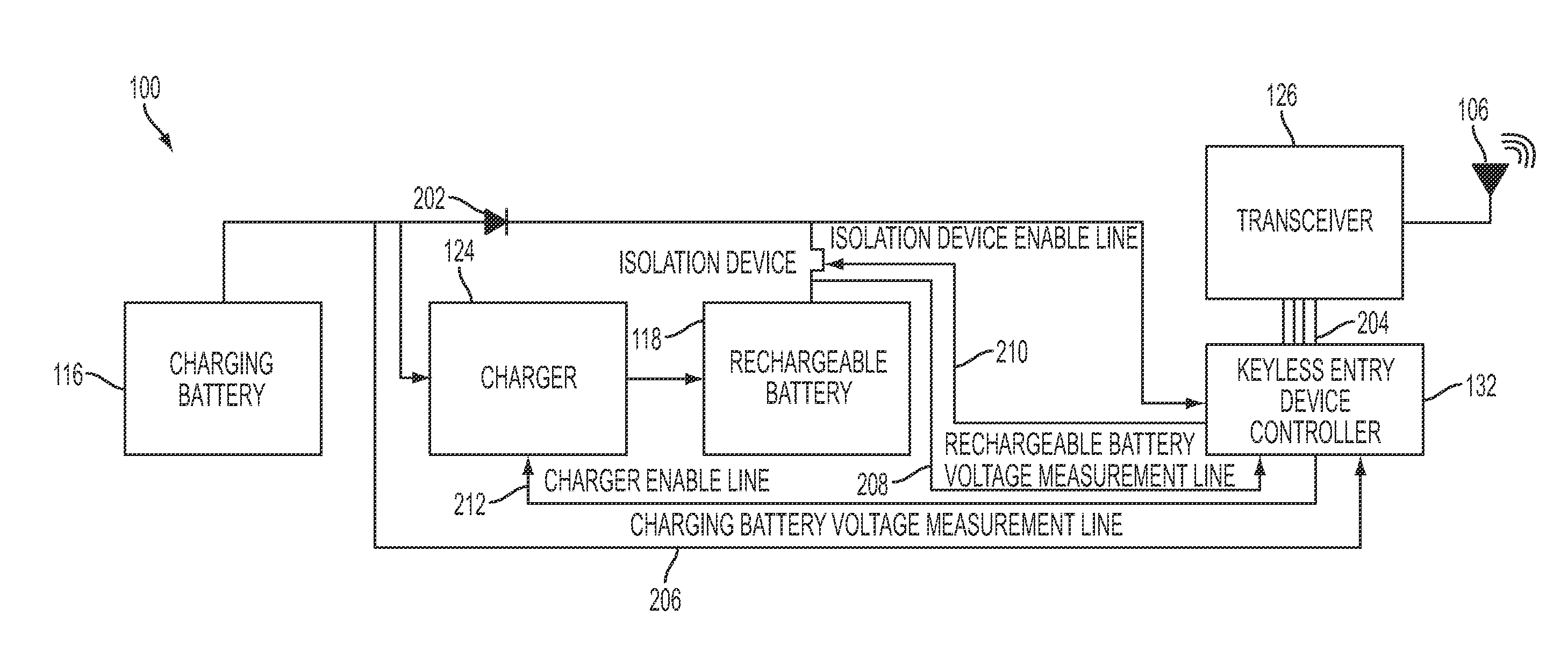
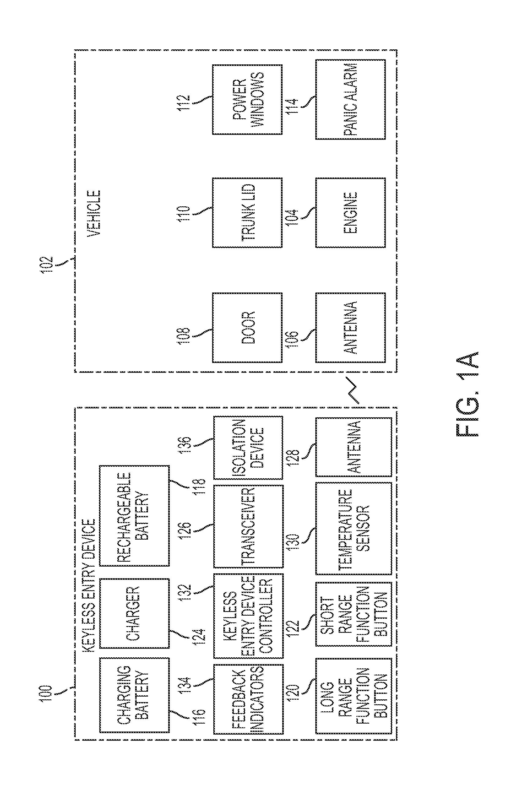
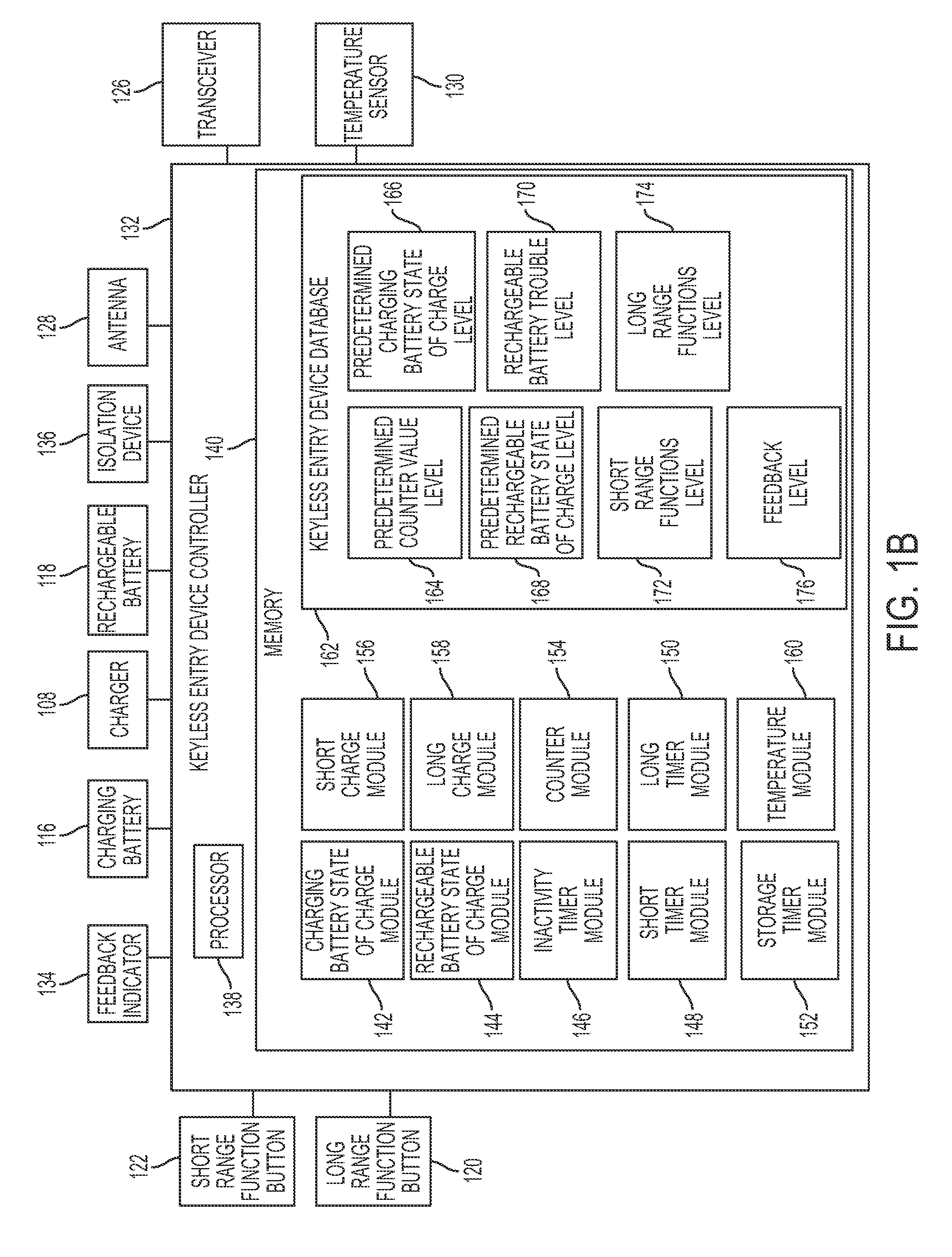
This patent describes a keyless entry device for a vehicle that has two batteries: a charging battery and a rechargeable battery. The device can switch between using the charging battery or the rechargeable battery depending on the function being selected. The rechargeable battery has a larger burst current delivery capacity than the charging battery, and can be used for both short range and long range functions. The device includes a battery charger for the rechargeable battery and two buttons: a short range button that causes the charging battery or the rechargeable battery to send a short range transmission, and a long range button that causes the charging battery or the rechargeable battery to send a long range transmission. The technical effect is to provide a more powerful and reliable keyless entry device for vehicles that can switch between the charging battery and the rechargeable battery based on the selected function.

Problems solved by technology

However, in some instances, the small battery cell cannot provide enough electric current for keyless entry devices that have higher electric current requirements (e.g., 80 mA), such as keyless entry devices that send high powered wireless long range transmissions.

Method used


Image

  • Keyless entry device and method for powering the keyless entry device
  • Keyless entry device and method for powering the keyless entry device
  • Keyless entry device and method for powering the keyless entry device

Examples


Embodiment Construction

[0016]Embodiments are now described with reference to the figures where like reference numbers indicate identical or functionally similar elements.

[0017]Reference in the specification to “one embodiment” or to “an embodiment” means that a particular feature, structure, or characteristic described in connection with the embodiments is included in at least one embodiment. The appearances of the phrase “in one embodiment” or “an embodiment” in various places in the specification are not necessarily all referring to the same embodiment.

[0018]A “bus”, as used herein, refers to an interconnected architecture that is operably connected to other computer components inside a computer or between computers. The bus can transfer data between the computer components. The bus can be a memory bus, a memory controller, a peripheral bus, an external bus, a crossbar switch, and / or a local bus, among others. The bus can also be a vehicle bus that interconnects components inside a vehicle using protoco...


PUM


Abstract

A keyless entry device and method for powering the keyless entry system, such as a key fob, are disclosed. The keyless entry device has a charging battery, a rechargeable battery, at least one long range function button for a long range function, and at least one short range function button for a short range function. The method includes charging the rechargeable battery using the charging battery, wherein the rechargeable battery has a larger burst current delivery capacity than the charging battery. The method further includes sending a short range transmission from the keyless entry device using at least one of: the charging battery, and the rechargeable battery, when the at least one short range function button is actuated. The method further includes sending a long range transmission from the keyless entry device at least one of: the charging battery, and the rechargeable battery, when the at least one long range function button is actuated.

Description

RELATED APPLICATIONS[0001]This application claims priority to U.S. Provisional Application Ser. No. 62 / 026,599 filed on Jul. 18, 2014, which is incorporated by reference herein.BACKGROUND[0002]Many vehicles utilize keyless entry devices. Presently, the industry standard for powering most keyless entry devices, such as a key fob, is to use a small battery cell, such as a lithium ion cell that is intended to sustain devices having a low electric current requirement (e.g., 10 mA). However, in some instances, the small battery cell cannot provide enough electric current for keyless entry devices that have higher electric current requirements (e.g., 80 mA), such as keyless entry devices that send high powered wireless long range transmissions.BRIEF DESCRIPTION[0003]According to one aspect, a method for powering a keyless entry device for a vehicle, includes providing the keyless entry device having a charging battery, a rechargeable battery, at least one long range function button for a ...

Claims


Application Information

Patent Timeline
Patent Type & Authority Applications(United States)
IPC IPC(8): H02J7/02G07C9/00H02J7/04
CPCH02J7/025H02J7/04G07C9/00007H02J50/80G07C9/00174G07C2009/00587G07C2009/00769H02J50/20G07C9/00182B60R25/24H02J7/1423G07C2009/00793G07C9/00309H02J7/342
Inventor LICKFELT, BRIAN K.YOSHIMURA, KENTAROSPANNBAUER, MICHAELGROEGER, DIRKSTETTER, ULRICH
Owner HONDA MOTOR CO LTD
Learn More