Electric power tool

a technology of electric power tools and power components, which is applied in the direction of manufacturing tools, electrical apparatus construction details, portable power-driven tools, etc., can solve the problems of reducing the heat radiation effect of the heat radiation member, and it is difficult to perform sufficient heat exchange, etc., to achieve convenient and/or convenient attachment work, easy to perform, and easy to attach

Active Publication Date: 2016-01-21
MAKITA CORP
View PDF2 Cites 11 Cited by
  • Summary
  • Abstract
  • Description
  • Claims
  • Application Information

AI Technical Summary

Benefits of technology

[0021]Because of this construction, the positioning of the circuit board with respect to the heat radiation member may be performed easily when the circuit board is attached to the heat radiation member. Therefore, the circuit board may be easily attached to the heat radiation member, and the attachment work may be easily and / or conveniently performed. Furthermore, other positioning member(s) and other positioning space(s) may not be necessary when the circuit board is attached to the heat radiation member. In this respect, the size of the controller may be advantageously reduced.
[0022]In another exemplary embodiment of the disclosure, a concave-convex shape may be formed on an outer surface part of the heat radiation member which is an opposite side of the facing part of the heat radiation member. Because of this construction, the surface area of the heat radiation member may be increased and the heat radiation effect of the electric components may be increased. Furthermore, it may be possible to suppress deformation (sink marks) generated due to the difference of the thickness when the heat radiation member is formed.
[0023]In another exemplary embodiment of the disclosure, the heat radiation member may be configured to serve as a case in which the circuit board is housed. Because of this construction, the circuit board may not be exposed and may be prevented from being damaged. Furthermore, the surface area of the heat radiation member may be defined to surround the circuit board. Accordingly, the heat radiation effect of the heat radiation member, and eventually of the circuit board including electric components may be increased.

Problems solved by technology

However, when the heat radiation member is simply reduced in size or thickness, it may be difficult to perform sufficient heat exchange, which may reduce the heat radiation effect by the heat radiation member.

Method used


Image

  • Electric power tool
  • Electric power tool
  • Electric power tool

Examples


Embodiment Construction

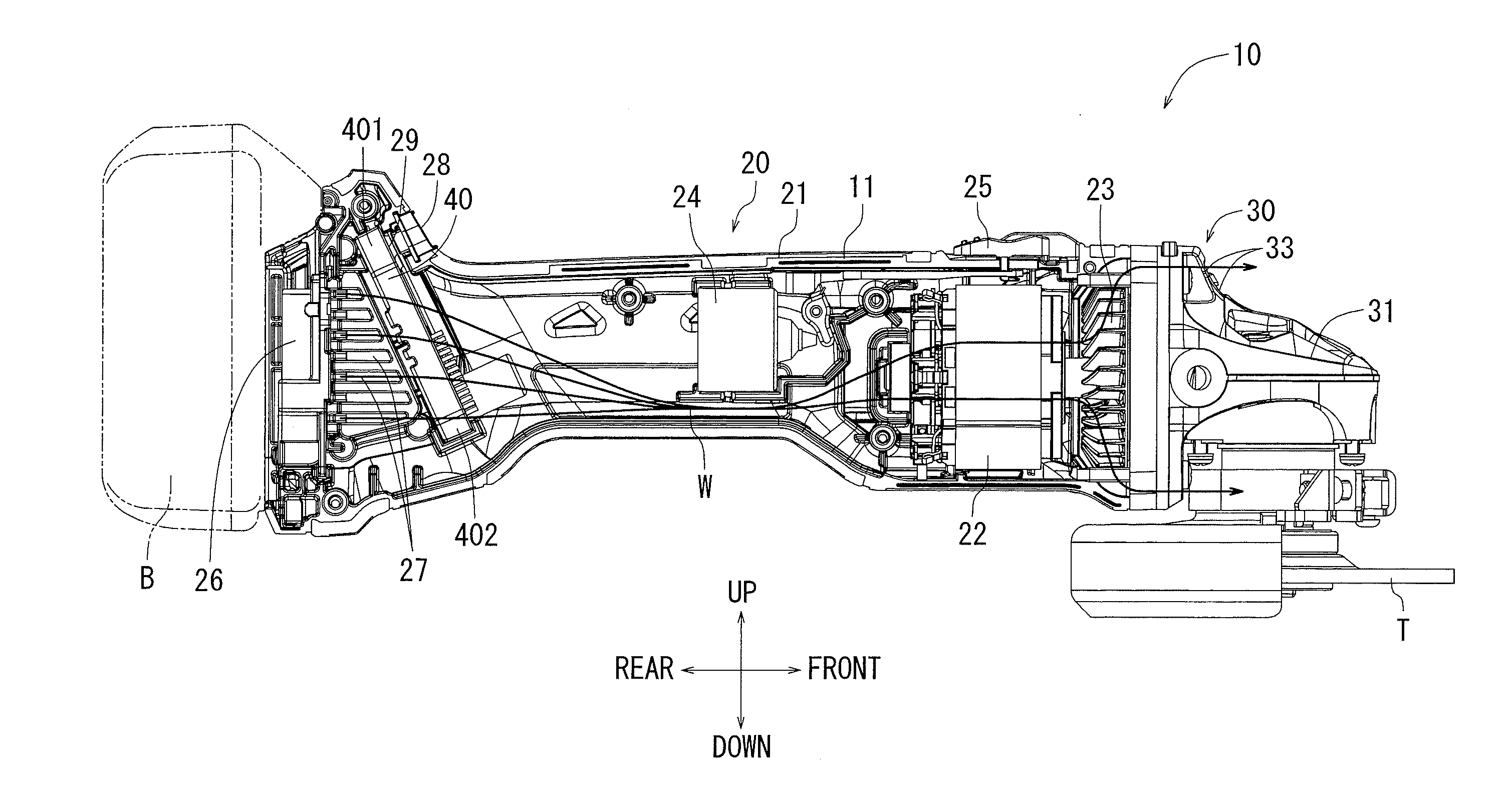
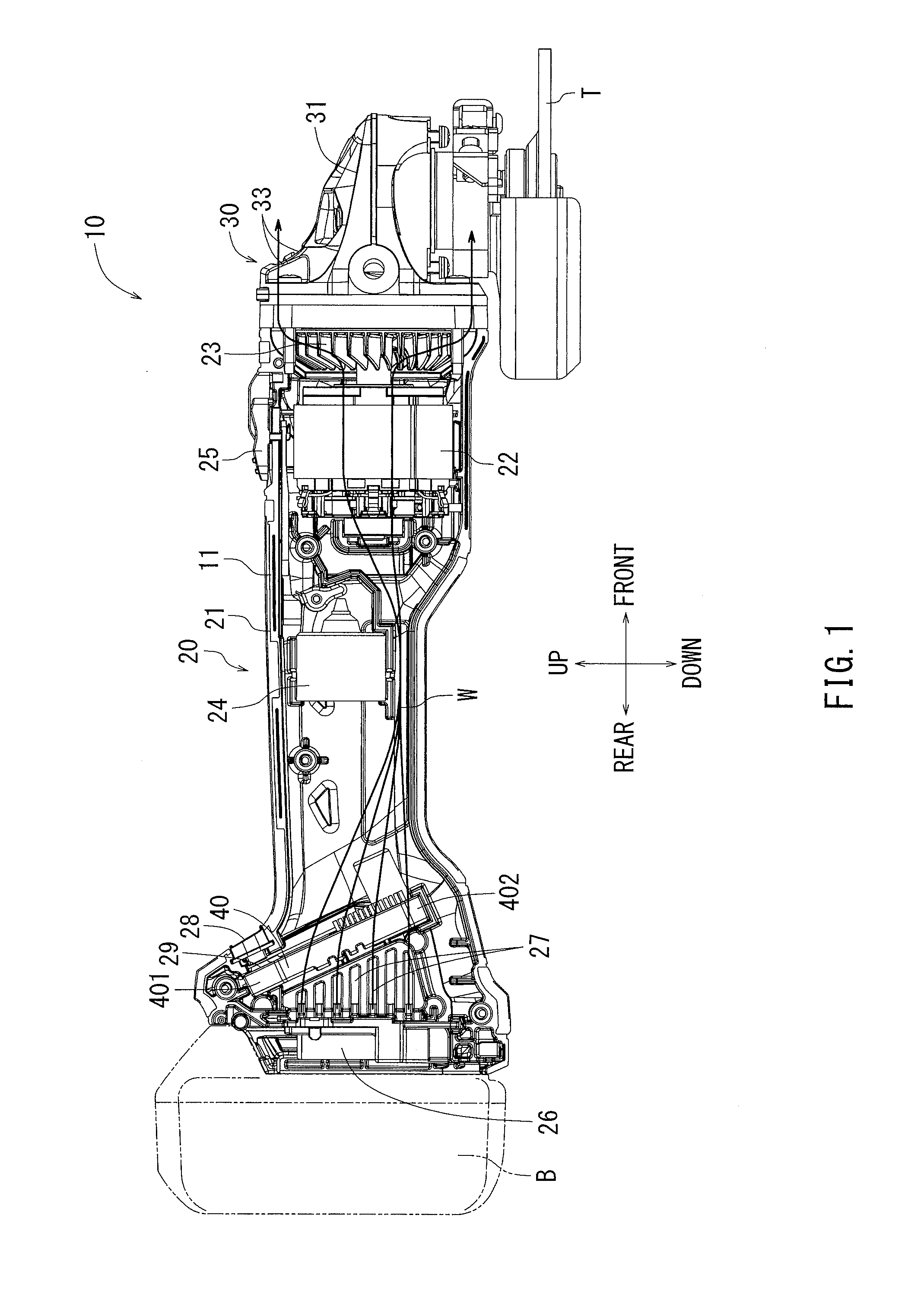
[0044]Hereinafter, an electric power tool according to one exemplary embodiment of the present teachings will be explained with reference to FIGS. 1 to 19. A half-cut internal structure view of FIG. 1 shows an internal structure of an electric power tool, such as a disc grinder 10, according to the present teachings. In the disc grinder 10 shown in FIG. 1, the some wirings are omitted such that the internal structure may be easily understood. The following explanation may be made referring to directions of front, rear, top, bottom, right and left written in the drawings. The disc grinder 10 is an electric power tool that may perform grinding and / or polishing by rotating a grindstone T using a brushless DC motor as a drive source. The disc grinder 10 may include a tool body 11 and a rechargeable battery B as a power source. The rechargeable battery B may be detachably attached to a battery attaching part 26 in a rear part of the tool body 11. The rechargeable battery B may be removed...


PUM


Abstract

In an electric power tool which houses a motor and a controller for controlling drive of the motor, the controller has a circuit board on which electric components are mounted and a heat radiation member which radiates heat of the electric components. The heat radiation member has a facing part which faces the circuit board in parallel to a board surface of the circuit board. The facing part is provided with steps by which a distance between the facing part and the board surface of the circuit board varies. Furthermore, the facing part of the heat radiation member is provided with a first facing part in which a relative distance with respect to the board surface of the circuit board is reduced.

Description

CROSS-REFERENCE[0001]This application claims priority to Japanese patent application Serial Number 2014-146680, filed on Jul. 17, 2014, the contents of which are incorporated herein by reference in their entirety.TECHNICAL FIELD[0002]The present invention generally relates to an electric power tool capable of driving a motor by a controller.BACKGROUND ART[0003]An electric power tool that includes an electric motor as a drive source is well known. Rotational drive of the electric motor is performed by a controller mounted in the electric power tool. The controller includes a circuit board that can control rotational drive of the electric motor. The circuit board includes a bridge circuit for controlling electric power to the electric motor (for example, refer to Japanese Laid-Open Patent Application No. 2009-214260). Generally, the controller may generate heat by the supplied electric power, and accordingly, a heat radiation member for radiating the heat is provided in the controller...

Claims


Application Information

Patent Timeline
Patent Type & Authority Applications(United States)
IPC IPC(8): H02K9/22H02K7/14H02K11/00
CPCH02K9/22H02K11/0073H02K7/145B24B23/028H05K7/20436H05K7/205B25F5/008H02K11/33H02K9/227
Inventor OMURA, MOTOHIROSUZUKI, RYOSUKETAGA, HIDEYUKI
Owner MAKITA CORP
Why Eureka
Try Eureka