Light emitting device driver circuit and control circuit and control method thereof

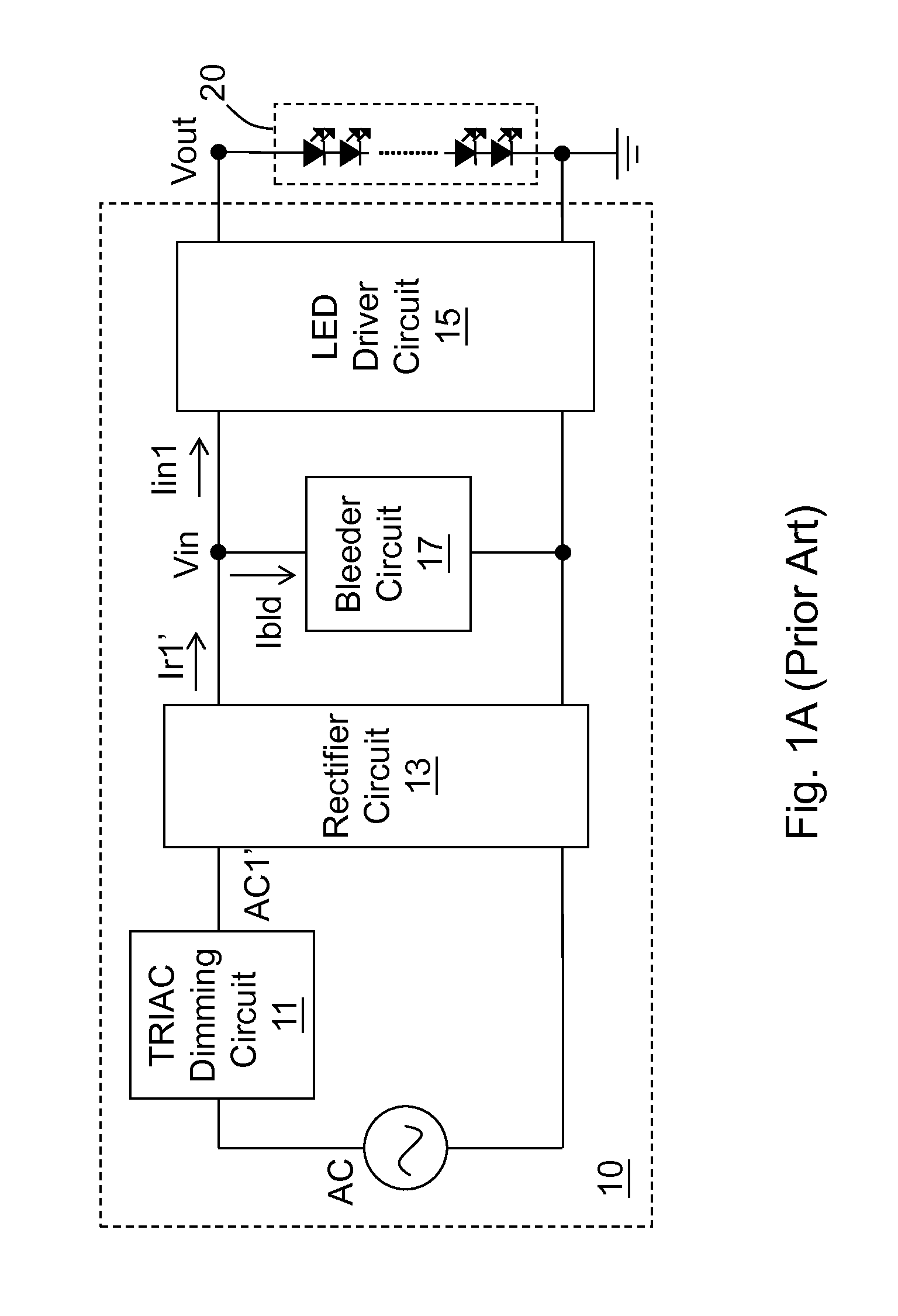
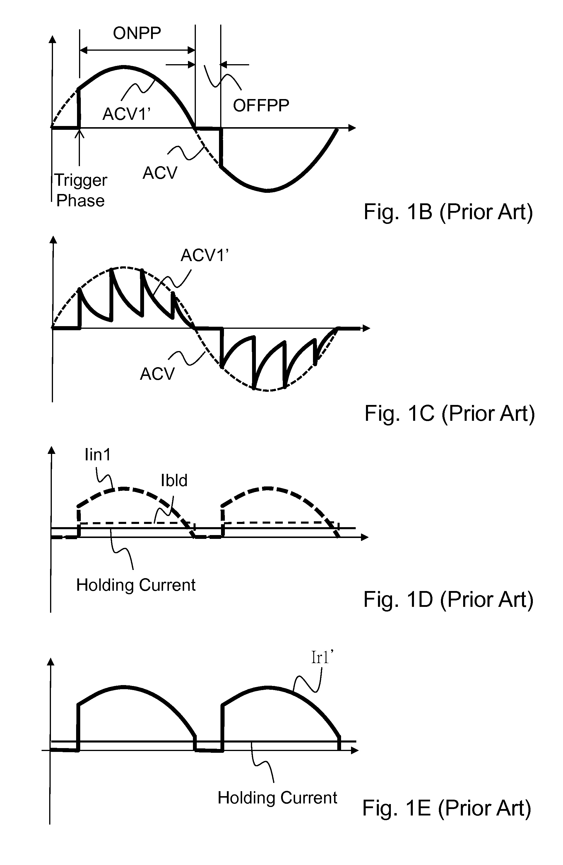
a technology of light emitting devices and driver circuits, which is applied in the direction of lighting devices, electrical devices, light sources, etc., can solve the problems of limited dimming range of led circuits b>20/b>, insufficient latching current and holding current of triac devices, and misfire still occurring,

Active Publication Date: 2016-01-21
RICHTEK TECH
View PDF0 Cites 5 Cited by
  • Summary
  • Abstract
  • Description
  • Claims
  • Application Information

AI Technical Summary

Benefits of technology

[0014]In one preferable embodiment, the CL signal is for maintaining the absolute leve

Problems solved by technology

One of the drawbacks of the aforementioned prior art is that the TRIAC dimming circuit 11 includes a TRIAC device which requires a large latching current to fire (start-up), and after the LED circuit 20 is turned ON in the ON phase period ONPP, it is required for the current flowing through the TRIAC device to have an absolute level higher than a holding current in order to keep the TRIAC dimming circuit 11 in a normal operation.
However if what the power supply drives is a low power consuming load circuit, such as the LED circuit 20, the latching current and the holding current for the TRIAC device is insufficient because of the low current of the LED circuit 20.
On the other hand, even t

Method used


Image

  • Light emitting device driver circuit and control circuit and control method thereof
  • Light emitting device driver circuit and control circuit and control method thereof
  • Light emitting device driver circuit and control circuit and control method thereof

Examples


first embodiment

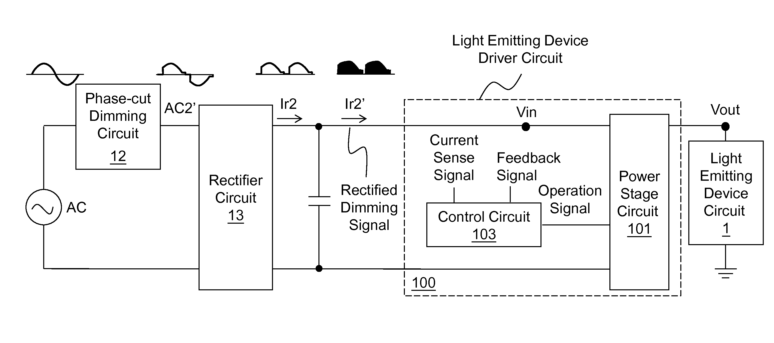
[0037]FIGS. 2A-2C show the present invention. As shown in FIG. 2A, alight emitting device driver circuit 100 drives a light emitting device circuit 1 according to a rectified dimming signal. A phase-cut dimming circuit 12 converts an AC signal to an AC dimming signal AC2′, wherein the phase-cut dimming circuit 12 is for example but not limited to the prior art TRIAC dimming circuit 11. The AC dimming signal AC2′ includes an AC dimming current flowing through the phase-cut dimming circuit 12. The phase-cut dimming circuit 12 blocks an OFF phase period OFFPP of the AC signal (as shown by the prior art OFF phase period OFFPP), and retains an ON phase period ONPP (as shown by the prior art ON phase period ONPP) of the AC signal, to generate the AC dimming signal AC2′. The rectifier circuit 13 converts the AC dimming signal AC2′ to the rectified dimming signal, wherein the rectifier circuit 13 is for example but not limited to abridge rectifier circuit, and the rectifier circuit 13 can o...

second embodiment

[0042]FIG. 3 shows the present invention. This embodiment shows a more specific embodiment of the light emitting device driver circuit 100. As shown in the figure, the power stage circuit 101 for example includes a first winding S1, a second winding S2, a third winding S3, and a power switch Q1. The first winding S1 is coupled to the rectifier circuit 13 and the power switch Q1, for receiving the rectified dimming signal and determining a switch current Ids flowing through the power switch Q1 according to the operation of the power switch Q1. The second winding S2 is coupled to the first winding S1, for generating the output signal including the output voltage Vout which is provided to the light emitting device circuit 1, according to the rectified dimming signal and the switch current Ids. The third winding S3 is coupled to the second winding S2, for generating a sense signal according to the output signal. As shown in the figure, in one non-limiting embodiment, the first winding S...

third embodiment

[0044]FIG. 4A shows the present invention. This embodiment shows a more specific embodiment of the control circuit 103. As shown in FIG. 4A, the control circuit 103 includes a pulse width modulation (PWM) circuit 1031, a current limit (CL) circuit 1033, and a determination circuit 1035. The PWM circuit 1031 is for generating a PWM signal according to a level of the feedback signal FB. The CL circuit 1033 is for generating a CL signal according to whether the current sense signal CS reaches a predetermined current threshold PCL. The determination circuit 1035 is coupled to the PWM circuit 1031 and the CL circuit 1033, for generating an operation signal GT according to the PWM signal and the CL signal, wherein the determination circuit 1035 determines the duty of the operation signal GT according to one of the PWM signal and the CL signal. The power stage circuit 101 operates the power switch Q1 according to the operation signal GT to maintain the absolute level of the AC dimming curr...


PUM


Abstract

The present invention provides a light emitting device driver circuit and a control circuit and a control method thereof. The light emitting device driver circuit is used for driving a light emitting device circuit according to a rectified dimming signal. The light emitting device driver circuit includes a power stage circuit and a control circuit. The control circuit includes a pulse width modulation (PWM) circuit, a current limit (CL) circuit, and a determination circuit. The CL circuit generates a CL signal according to a current sense signal and a predetermined CL threshold. The determination circuit is coupled to the PWM circuit and the CL circuit, for generating an operation signal according to a PWM signal and the CL signal. The power stage circuit maintains an absolute level of an AC dimming current not lower than a holding current in an ON phase period.

Description

CROSS REFERENCE[0001]The present invention claims priority to U.S. provisional application No. 62 / 025275, filed on Jul. 16, 2014.BACKGROUND OF THE INVENTION[0002]1. Field of Invention[0003]The present invention relates to a light emitting device driver circuit and a control circuit and a control method thereof. Particularly, it relates to such light emitting device driver circuit and control circuit and control method thereof which improve a dimmable range of the light emitting device circuit.[0004]2. Description of Related Art[0005]FIG. 1A shows a schematic diagram of a prior art light emitting diode (LED) power supply circuit 10. As shown in FIG. 1A, the LED power supply circuit 10 includes a tri-electrode AC switch (TRIAC) dimming circuit 11, a rectifier circuit 13, an LED driver circuit 15, and a bleeder circuit 17. The TRIAC dimming circuit 11 receives an AC signal AC and outputs an AC dimming signal AC1′. When the AC signal exceeds a trigger phase, the TRIAC dimming circuit 11...

Claims


Application Information

Patent Timeline
IPC IPC(8): H05B44/00
CPCH05B33/0818H05B33/0851H05B45/10H05B45/3725H05B45/14
Inventor WU, CHANG-YUCHIU, WEI-MING
Owner RICHTEK TECH
Why Eureka
Try Eureka