Dynamic load carriage frame

a load carriage and frame technology, applied in the field of load carriage frames, can solve the problems of heavy body armour vests, uncomfortable shoulders, belt use, etc., and achieve the effects of reducing fatigue, reducing load carriage injuries and stress, and improving the overall operational performance or efficiency of wearers

Inactive Publication Date: 2016-01-28
BCB INT
View PDF10 Cites 11 Cited by
  • Summary
  • Abstract
  • Description
  • Claims
  • Application Information

AI Technical Summary

Benefits of technology

[0014]The invention relates especially to a load transfer frame that can be integrated into an armour vest and can transfer weight from the shoulder straps of a rucksack or other secondary load to the waist belt that in turn transfers the load to the wearer's pelvic girdle. The belt can be used to support traditional belt-kit and have other loads such as pouches attached directly to it.
[0015]Advantageously, a preferred embodiment of the present invention provides a low-cost, low part-count, portable, lightweight and comfortable load transfer system that helps reduce load carriage injuries and stress, thereby improving the overall operational performance or efficiency of the wearer. Beneficially, the simplicity of construction and the flexible nature of the materials used to produce the device allow the wearer to move freely without impinging on any dexterity. Furthermore, the self-contained nature of the system means that the load carriage system is without tethers or restrictive ties.
[0016]The present invention provides a solution to load support by selectively transferring some of the weight of the vest and/or any external load to the wearer's pelvic girdle, especially through the provision of a self-adjusting back brace. In ot...

Problems solved by technology

Current body armour vests are heavy.
However, the wearing of body armour vests prevents the use of belts as the armour covers the waist.
High pressure on the shoulders is u...

Method used


Image

  • Dynamic load carriage frame
  • Dynamic load carriage frame
  • Dynamic load carriage frame

Examples


Embodiment Construction

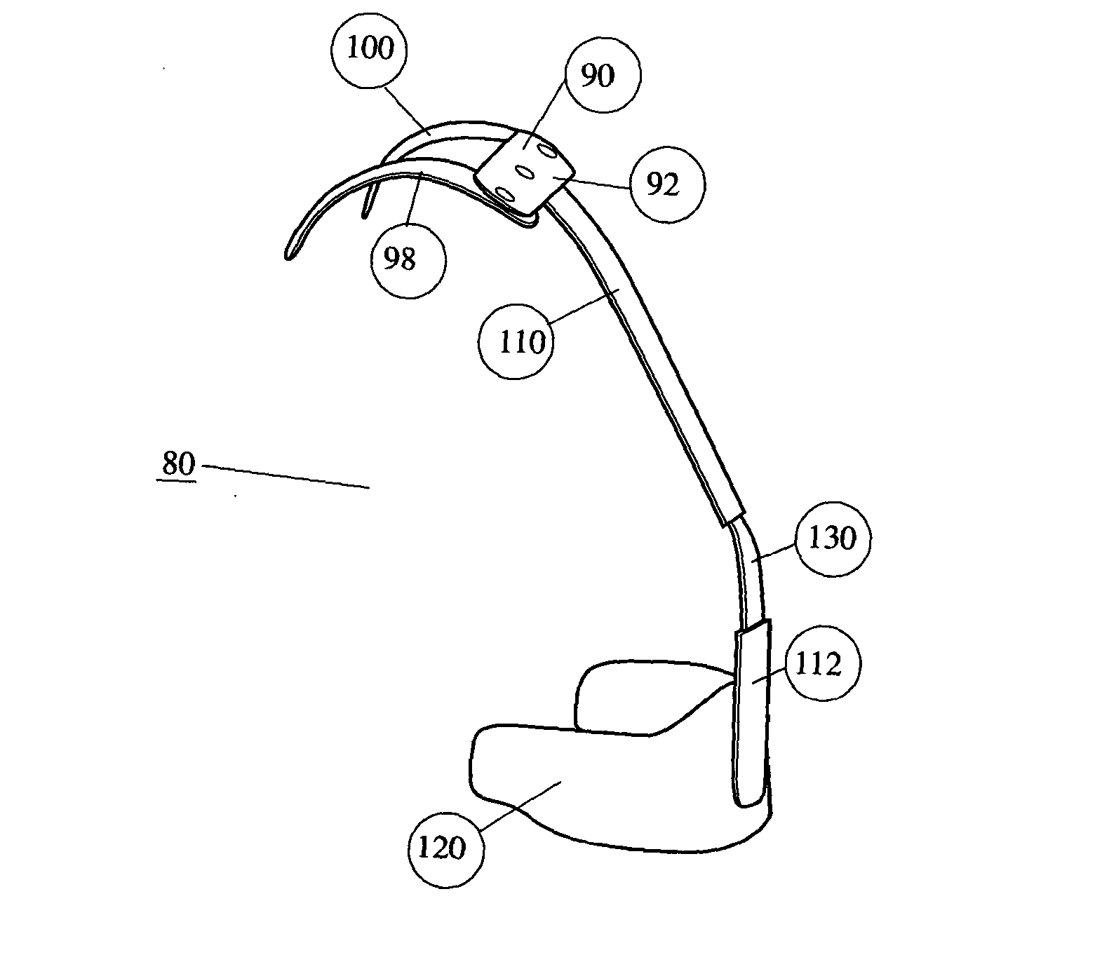
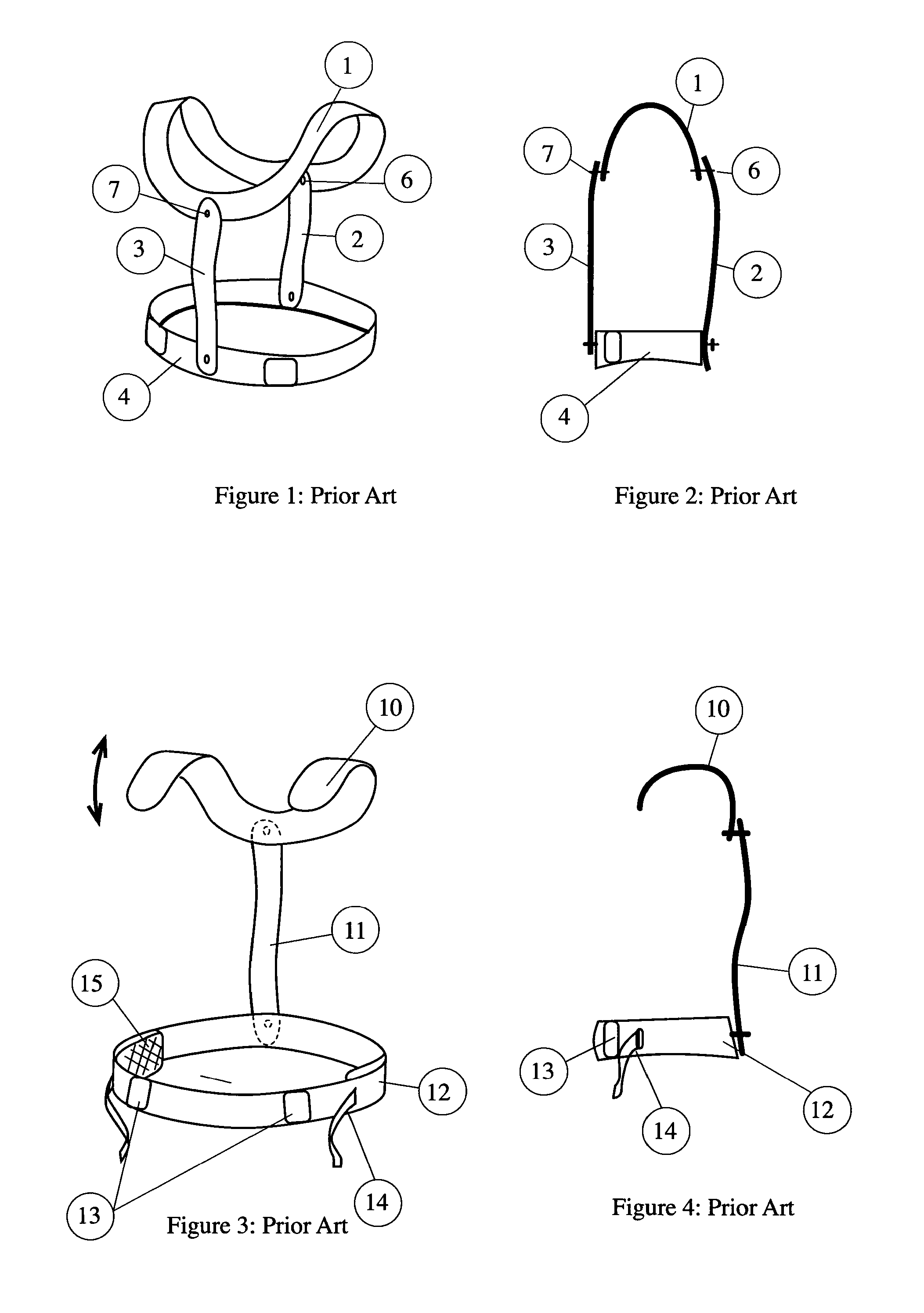
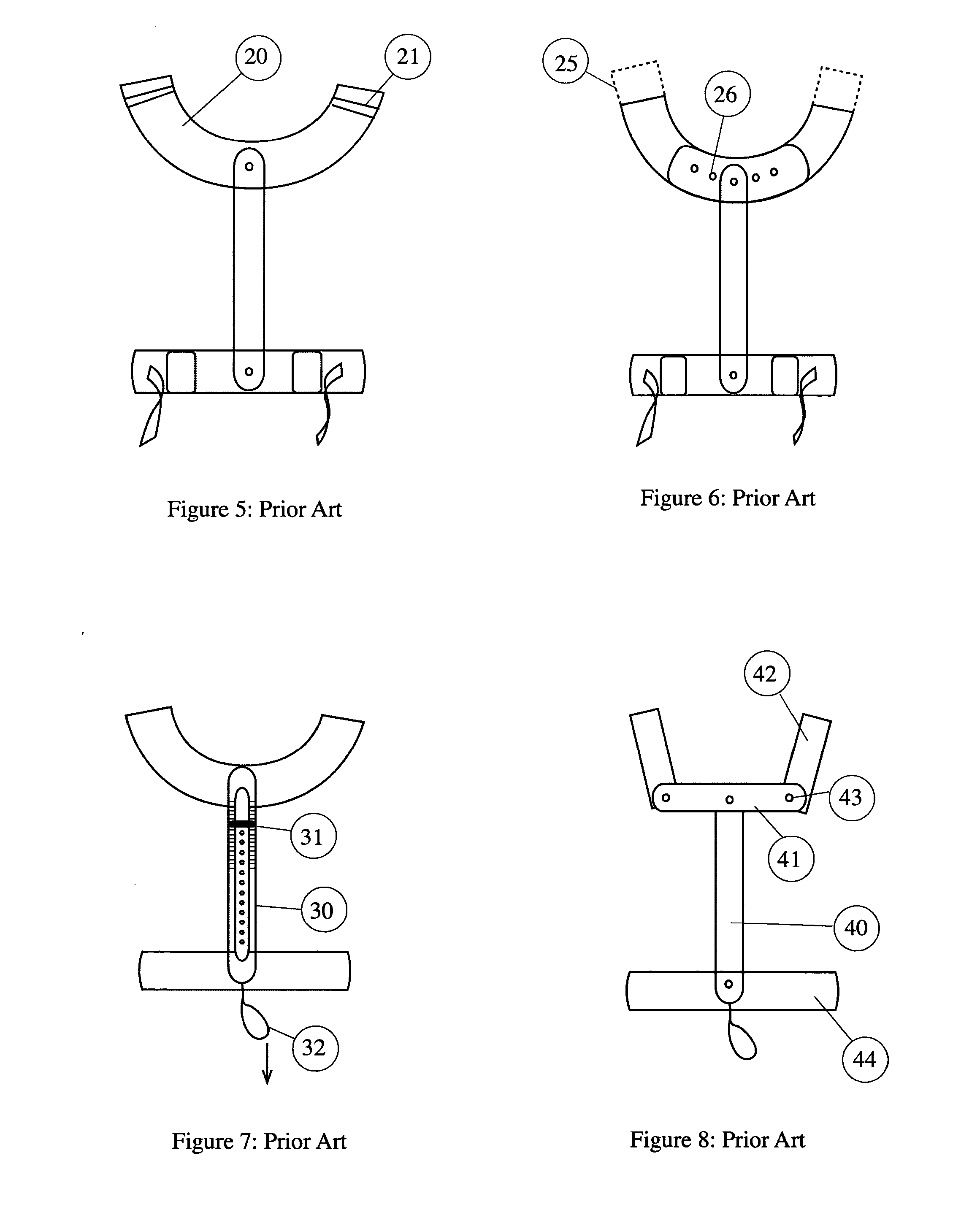
[0037]To provide a context for the invention, reference is made to FIGS. 1 to 8 that describe devices and systems for transferring weight from the shoulders of the wearer to the pelvic girdle of the wearer. The device is particularly applicable to a load carriage for supporting armour vest or the like. The weight distribution system, in overview, comprises an adjustable padded belt secured to a load bearing back brace that in turn is attached to a shoulder yoke. The yoke supports the weight of the vest via the shoulders of the armour and any other load such as a rucksack and transfers the weight via the back brace to the belt and the wearer's pelvic girdle. The yoke covers the shoulders (of the wearer) and is mounted either above the armour and attached to it by tension members or the yoke is mounted below the armour and holds the armour up. A soft armour pack of the armour vest can either be located inside or outside of the weight distribution device. In cases where the armour pack...


PUM


Abstract

A load carriage frame (80) of FIG. 9 includes a shoulder yoke (90) and a belt (120) separated from the yoke by a multi-element connecting brace (96). The brace is telescopic in nature in that a flexible but rigid tongue (130), extending from a first section, is permitted to slide within a guide on a second section (154), thereby allowing the length of the connecting brace to be altered. The multi-element connecting brace is centrally coupled to the yoke and centrally coupled to the belt and configured to act as a force path by transferring weight that, in use, is loaded onto or through the yoke and into the belt thereby effecting selected weight re-distribution onto the pelvic girdle of a wearer about which the belt, in use, is secured. Additionally, as shown in FIG. 20, a quick release mechanism may further alter the length of the connecting brace by allowing the position of a rotational coupling point to be altered relative to a housing of the quick release mechanism. The quick release mechanism can, in fact, be used with a single piece connecting brace.

Description

BACKGROUND TO THE INVENTION[0001]The present invention relates to a load carriage frame and specifically, but not exclusively, to a load carriage frame used when wearing armour vests or otherwise in generally supporting carriage of a user-worn load, such as a rucksack. The invention is particularly applicable to an active or dynamic load carriage frame used by infantrymen in hostile military operations.SUMMARY OF THE PRIOR ART[0002]Current body armour vests are heavy. Additionally a person who is wearing a vest incorporating body armour may have to carry a rucksack or other load. This load can to attached directly to the vest or be a separate item. The weight of the vest and the weight of the additional load is presently carried on the shoulders of the wearer. It is well known by physiologists and those skilled in the art that it is preferable to support at least some of the load on the pelvic girdle rather than solely on the shoulders. Some rucksacks are fitted with belts to transf...

Claims


Application Information

Patent Timeline
IPC IPC(8): A45F3/10A45F3/14
CPCA45F3/14A45F3/10A45F3/08
Inventor SEARLE, MATTHEWLEWIS, CHRISTOPHER MARK
Owner BCB INT
Why Eureka
Try Eureka