

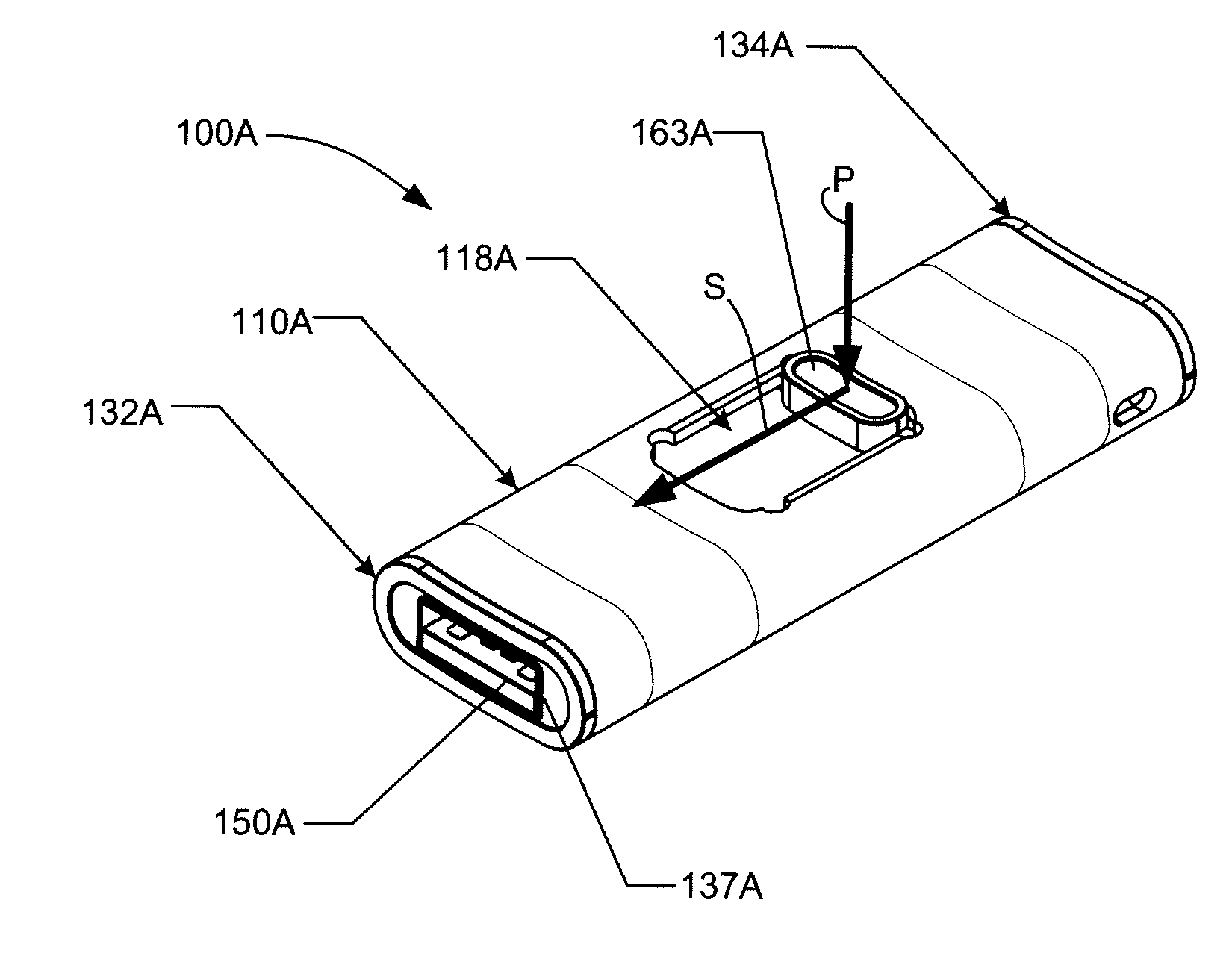
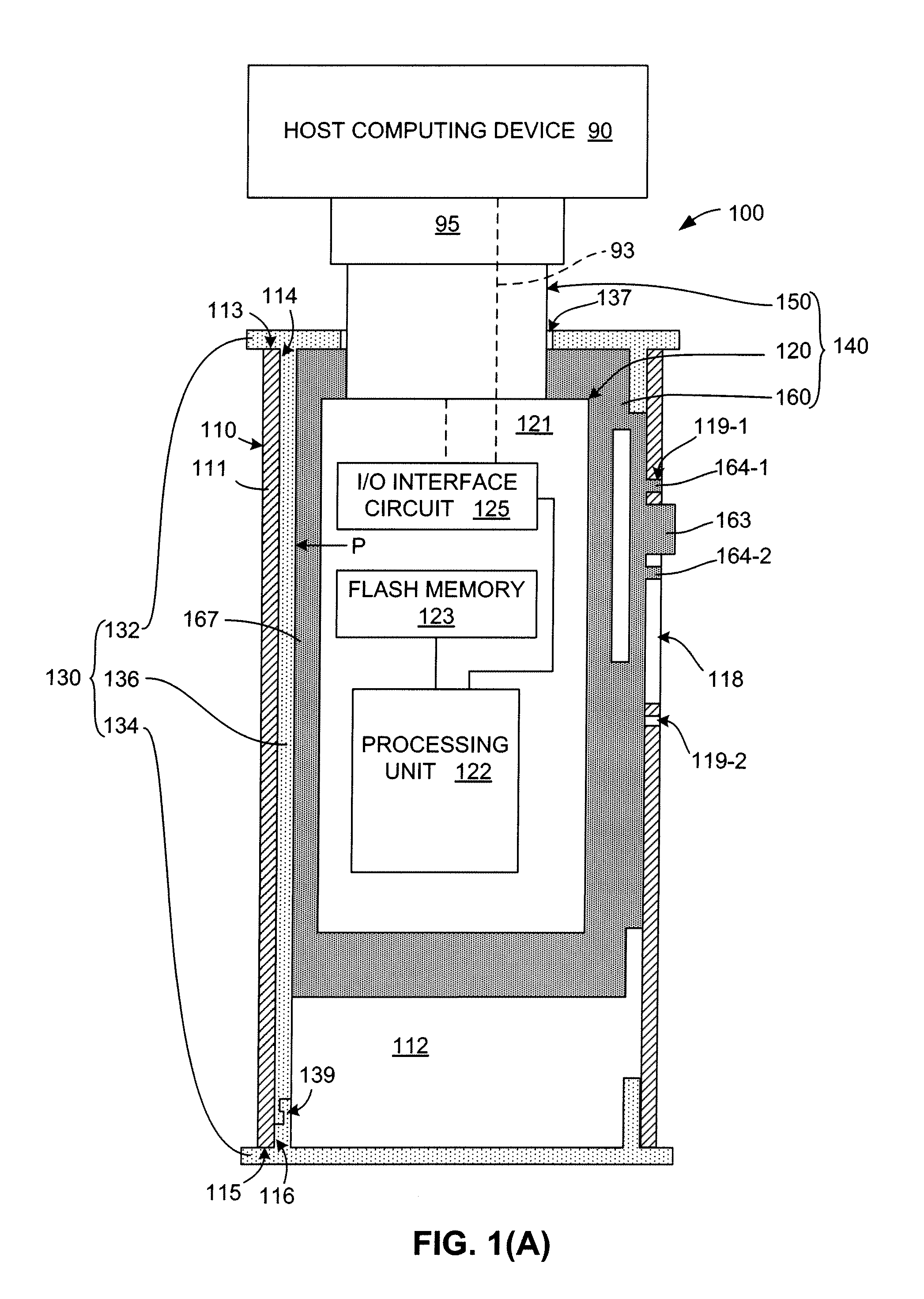
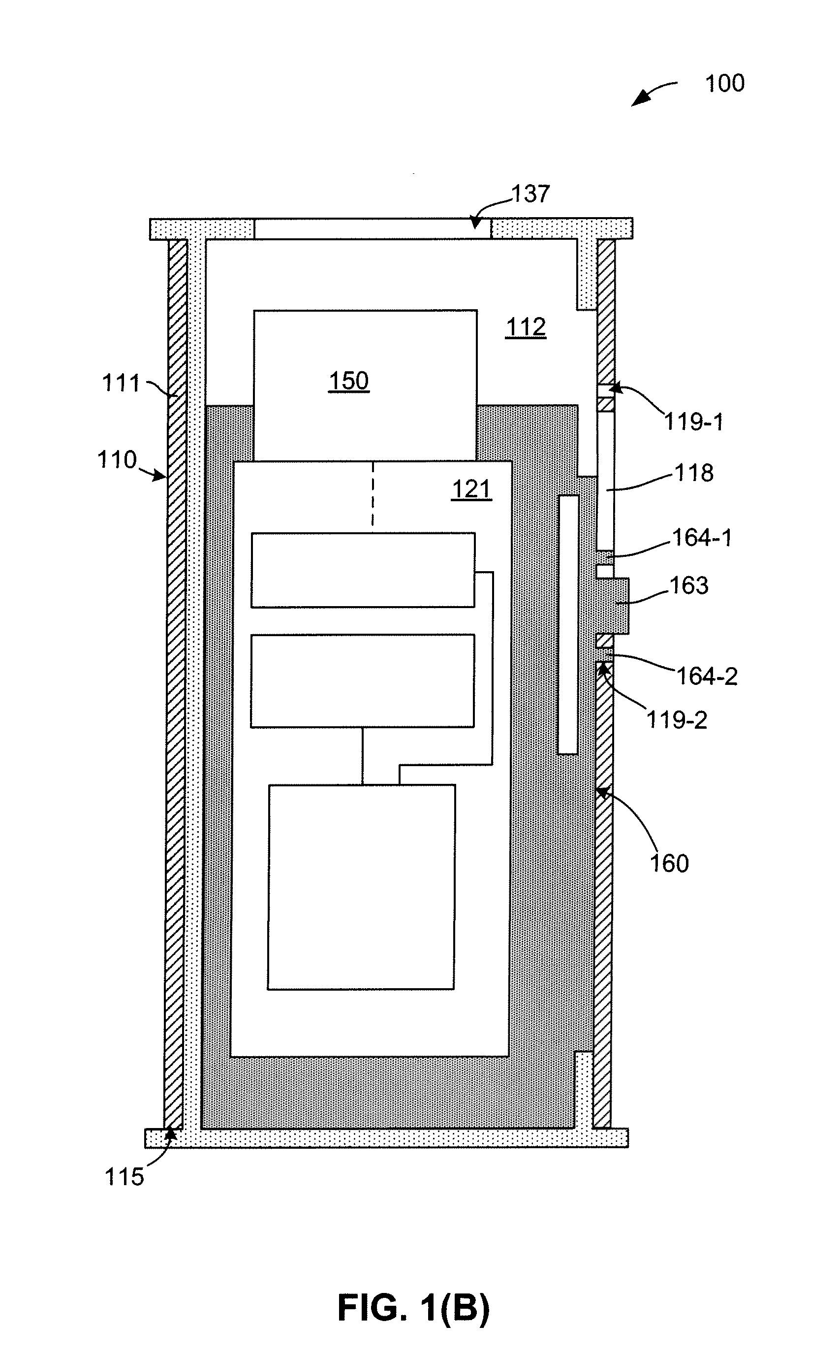
Press-Push Flash Drive Apparatus With Metal Tubular Casing And Snap-Coupled Plastic Sleeve
a flash drive and metal tubular casing technology, applied in the direction of electrical apparatus casing/cabinet/drawer, memory adressing/allocation/relocation, coupling device connection, etc., can solve the problems of inability to fully utilize flash memory, limited life span of flash memory sectors, and inability to quickly access flash memory, so as to avoid excessive wear and early failure, prevent cuts or other injuries, and protect the effect of durability and reliability
- Summary
- Abstract
- Description
- Claims
- Application Information
AI Technical Summary
Benefits of technology
Problems solved by technology
Method used
Image

Examples
Embodiment Construction
[0049]The present invention relates to an improvement in flash memory devices such as USB flash drives. The following description is presented to enable one of ordinary skill in the art to make and use the invention as provided in the context of a particular application and its requirements. As used herein, directional terms such as “upper”, “upwards”, “lower”, “downward”, “front”, “rear”, are intended to provide relative positions for purposes of description, and are not intended to designate an absolute frame of reference. In addition, the phrases “integrally connected” and “integrally molded” is used herein to describe the connective relationship between two portions of a single molded or machined structure, and are distinguished from the terms “connected” or “coupled” (without the modifier “integrally”), which indicates two separate structures that are joined by way of, for example, adhesive, fastener, clip, or movable joint. Various modifications to the preferred embodiment wil...
PUM
 Abstract
Description
Claims
Application Information