Leadless wireless ECG measurement system and method for measuring of bio-potential electrical activity of the heart

Inactive Publication Date: 2016-01-28
KHAIR MOHAMMAD
View PDF7 Cites 33 Cited by
  • Summary
  • Abstract
  • Description
  • Claims
  • Application Information

AI Technical Summary

Benefits of technology

The present invention is a leadless wireless ECG measurement system and method that uses less separation distance between electrodes, resulting in improved design and performance. It is more compact, comfortable for patients, easier to use, and has more flexibility of placement for clinicians without compromising accuracy. The system has a smaller footprint than conventional devices and produces higher degrees of comfort and flexibility.

Problems solved by technology

In early years, this was necessary for measurement of ECG due to lack of electronics that satisfy the measurement quality, signal-to-noise ratio, and cost constraints.
One of the disadvantages encountered in the operation of the conventional ECG devices is that they utilize a large separation between the electrode contact points which requires maximum surface area of the skin and thus maximizes impedance and measured voltage potential across the contact electrodes.
Another disadvantage suffered by the prior art ECG devices is that the numerous lengthy terminal wires coupled to the electrodes will frequently obstruct the patient and limit the freedom of movement of the patient.
Further, the terminal wires often become intertangled with one another during their use, thereby rendering them difficult and cumbersome for the physician and / or technician.
In addition, the conventional ECG devices and their attaching electrodes suffer from the problem of having a relatively large footprint.

Method used


Image

  • Leadless wireless ECG  measurement system and method for measuring of bio-potential electrical activity of the heart
  • Leadless wireless ECG  measurement system and method for measuring of bio-potential electrical activity of the heart
  • Leadless wireless ECG  measurement system and method for measuring of bio-potential electrical activity of the heart

Examples


Embodiment Construction

[0038]Before explaining the disclosed embodiments in detail, it is to be distinctly understood at the outset that the present invention shown in the drawings and described in detail in association with a leadless wireless ECG system for measuring of bio-potential electrical activity of the heart is not intended to serve as a limitation upon the scope or teachings thereof, but is to be considered merely for the purpose of convenience of illustration of one example of its application.

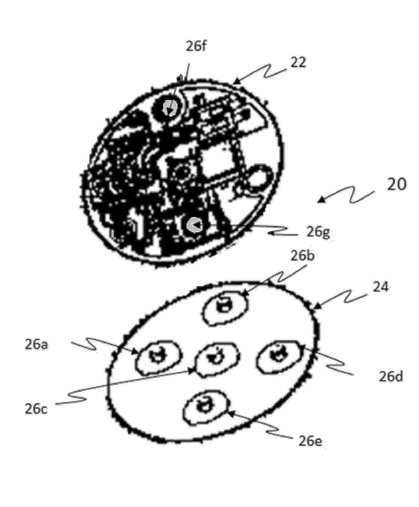
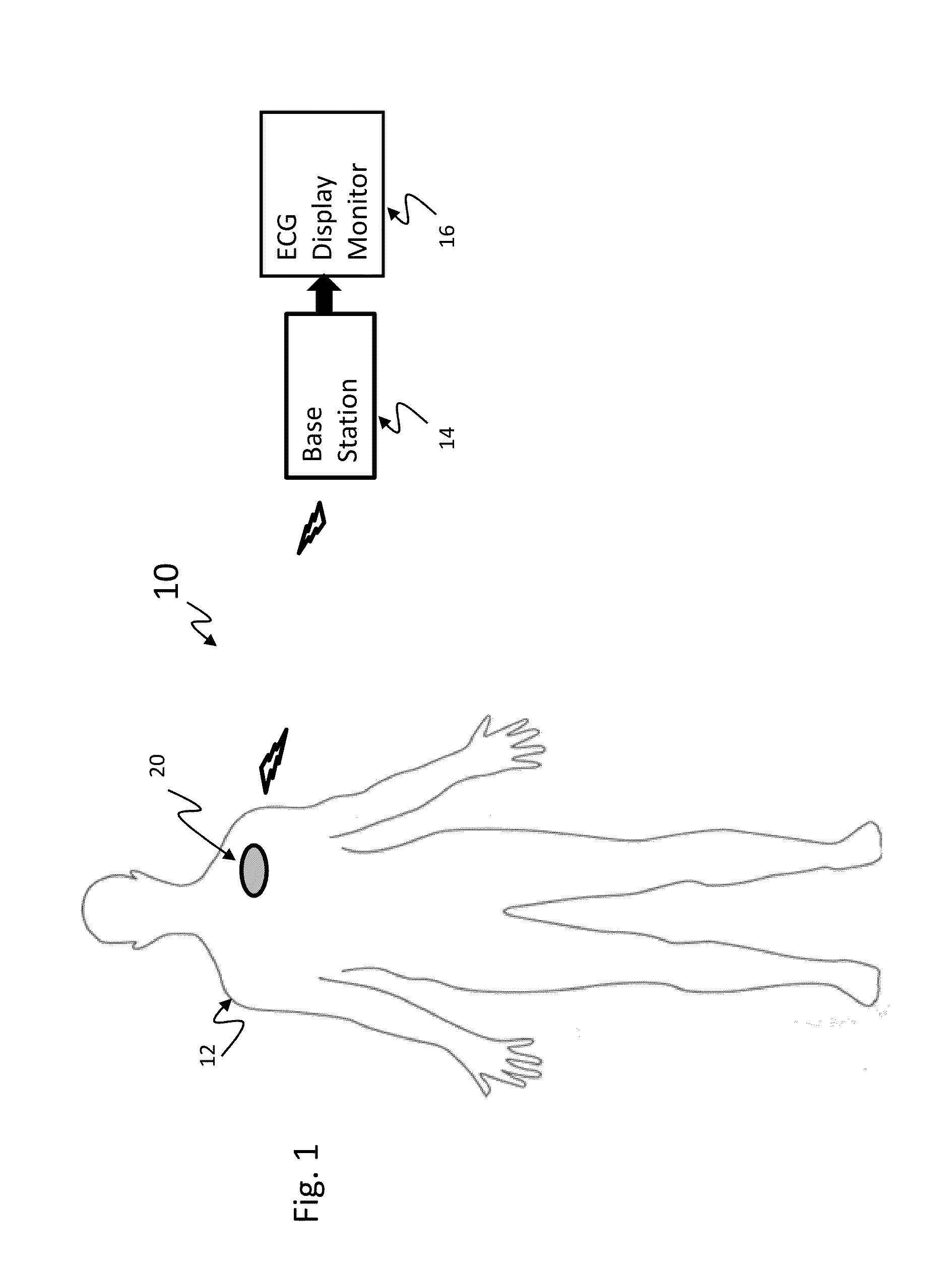
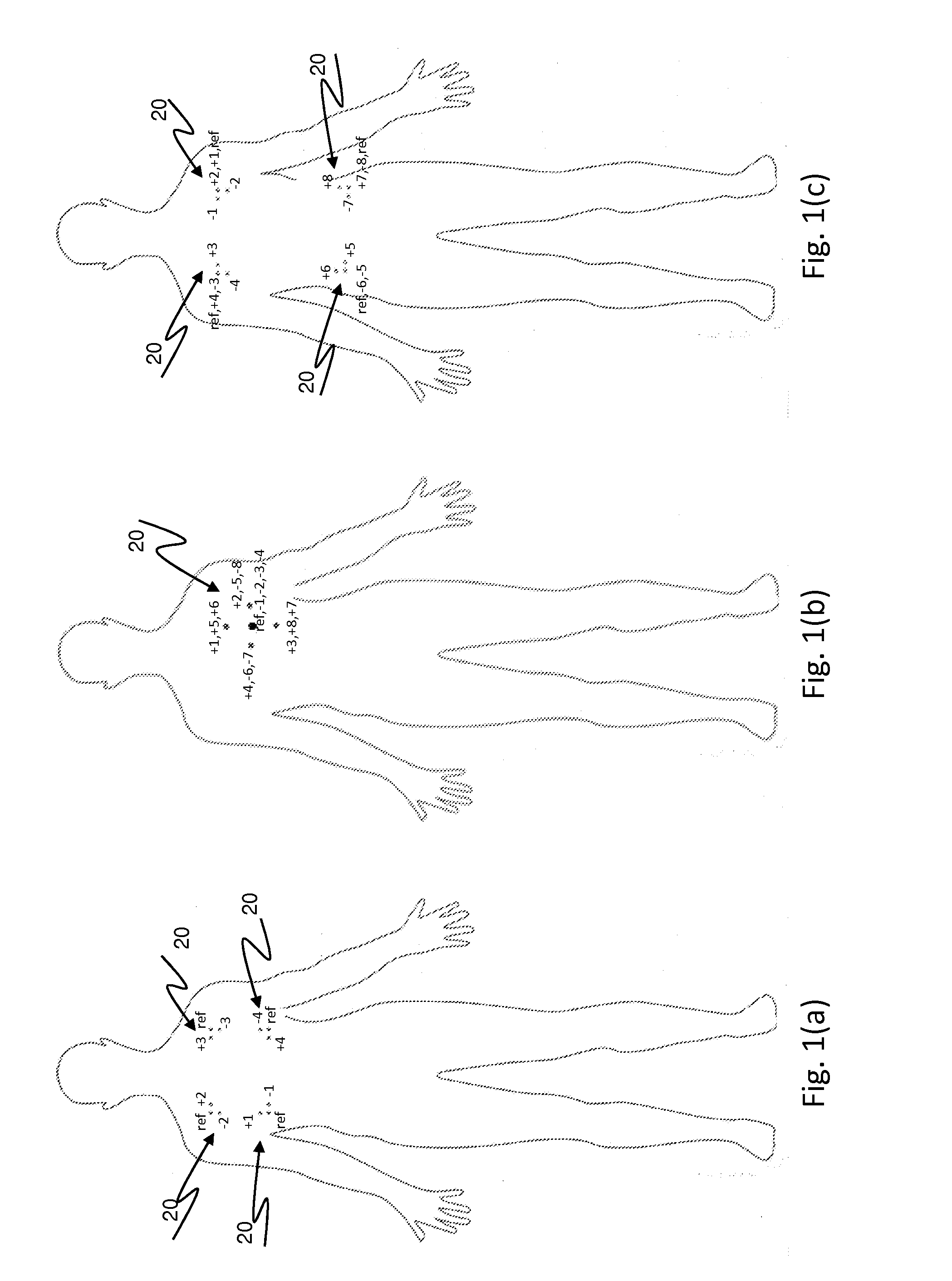
[0039]Referring now in detail to the various views of the drawings, there is illustrated in FIG. 1 a leadless wireless ECG measurement system for measuring of bio-potential electrical activity of the heart in a patient's body, which is designated generally by reference numeral 10 and is constructed in accordance with the principles of the present invention. The ECG measurement system 10 acquires “short-lead” ECG heart-signals from the body 12 of the patient and transmits them wirelessly to a receiving bas...


PUM


Abstract

A leadless wireless ECG measurement system for measuring of bio-potential electrical activity of the heart in a patient's body includes at least one multi-contact bio-potential electrode assembly adapted for attachment to the patient's body. The electrode assembly is formed of an electronic patch layer and a disposable electrode layer. The disposable electrode layer has a plurality of contact points for engagement with the surface of the patient's body and is configured to measure short-lead ECG signals in response to electrical activity in the heart. A processing unit is provided and is configured to produce a transfer function which computes estimated long-lead ECG signals based on the measured short-lead ECG signals from the plurality of contact points.

Description

CROSS-REFERENCE TO RELATED APPLICATIONS[0001]This application is a non-provisional application which claims the benefits of provisional applications Ser. No. 61 / 460,233 filed on Dec. 28, 2010 and Ser. No. 61 / 460,254 filed on Dec. 28, 2010.BACKGROUND OF THE INVENTION[0002]1. Technical Field[0003]This invention relates generally to wireless ECG bio-potential measurement devices for measuring electrical bio-potential signals generated by the heart. More particularly, it relates to a new and improved leadless wireless ECG measurement system and method for measuring of bio-potential electrical activity of the heart that uses measurements obtained across a much smaller separation distance between electrode contact points, but yet retains the presentation of ECG waveforms which corresponds closely to existing ECG measurement standards, thereby preserving the waveform morphology, amplitude, and frequency components.[0004]2. Prior Art[0005]As is generally known in the art, an electrocardiogr...

Claims


Application Information

Patent Timeline
IPC IPC(8): A61B5/0408A61B5/00A61B5/04A61B5/0476A61B5/0488A61B5/0496A61B5/145
CPCA61B5/0408A61B5/145A61B5/0476A61B5/0488A61B5/04012A61B5/04001A61B5/0006A61B5/742A61B5/0496A61B5/30A61B5/282A61B5/316A61B5/369A61B5/25A61B5/24A61B5/389A61B5/398
Inventor KHAIR, MOHAMMAD
Owner KHAIR MOHAMMAD
Why Eureka
Try Eureka