
Rigid composite structure for magnetic coupler

a composite structure and magnetic coupler technology, applied in the direction of mould fastening means, ceramic shaping apparatus, printing, etc., can solve the problems of insufficient concrete release, steel inserts can rust, and extra labor is required to separate steel inserts from the concrete structure created

Inactive Publication Date: 2016-01-28
KEGERIS THEODORE L
View PDF1 Cites 3 Cited by
  • Summary
  • Abstract
  • Description
  • Claims
  • Application Information

AI Technical Summary

Benefits of technology

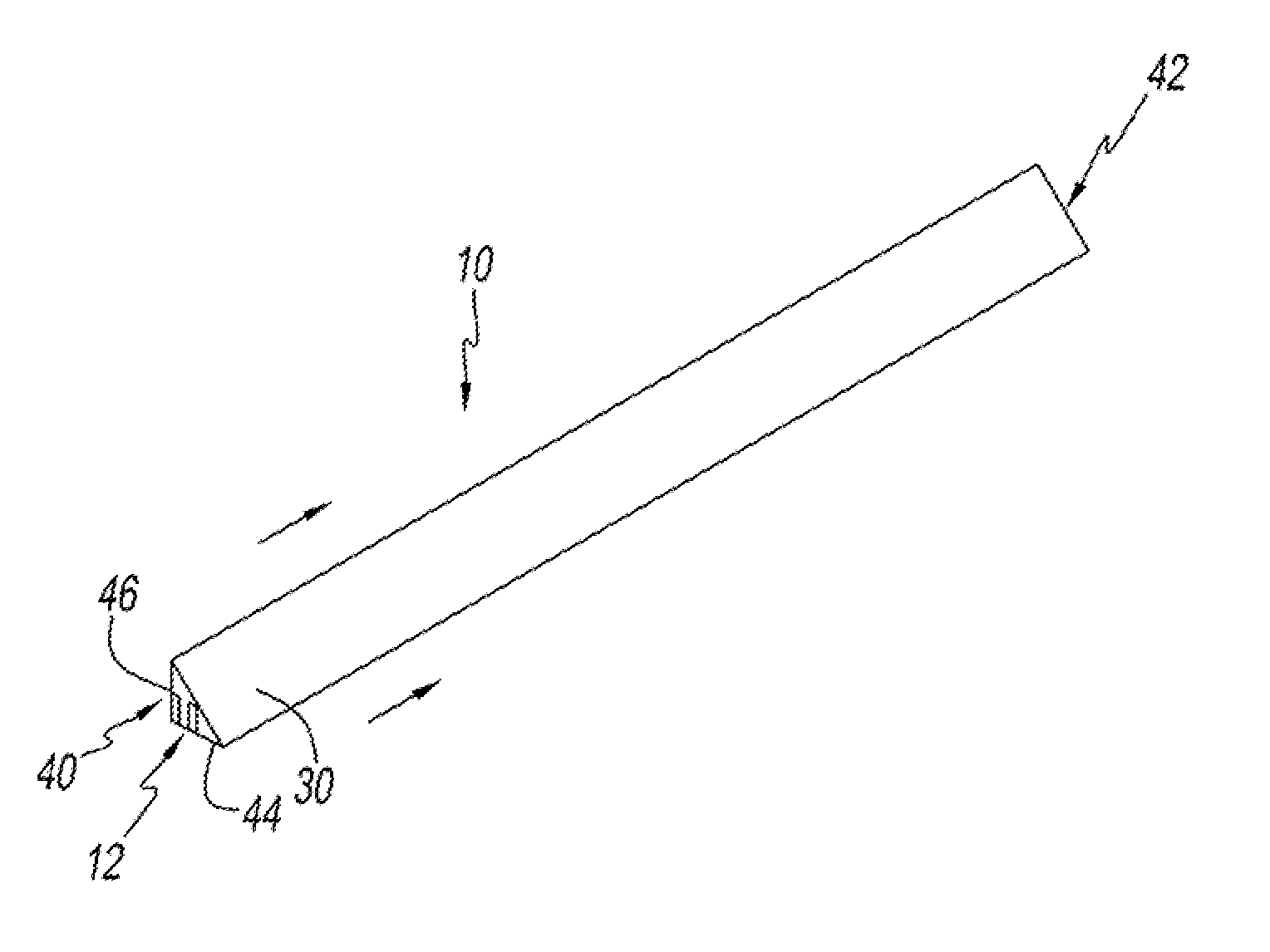
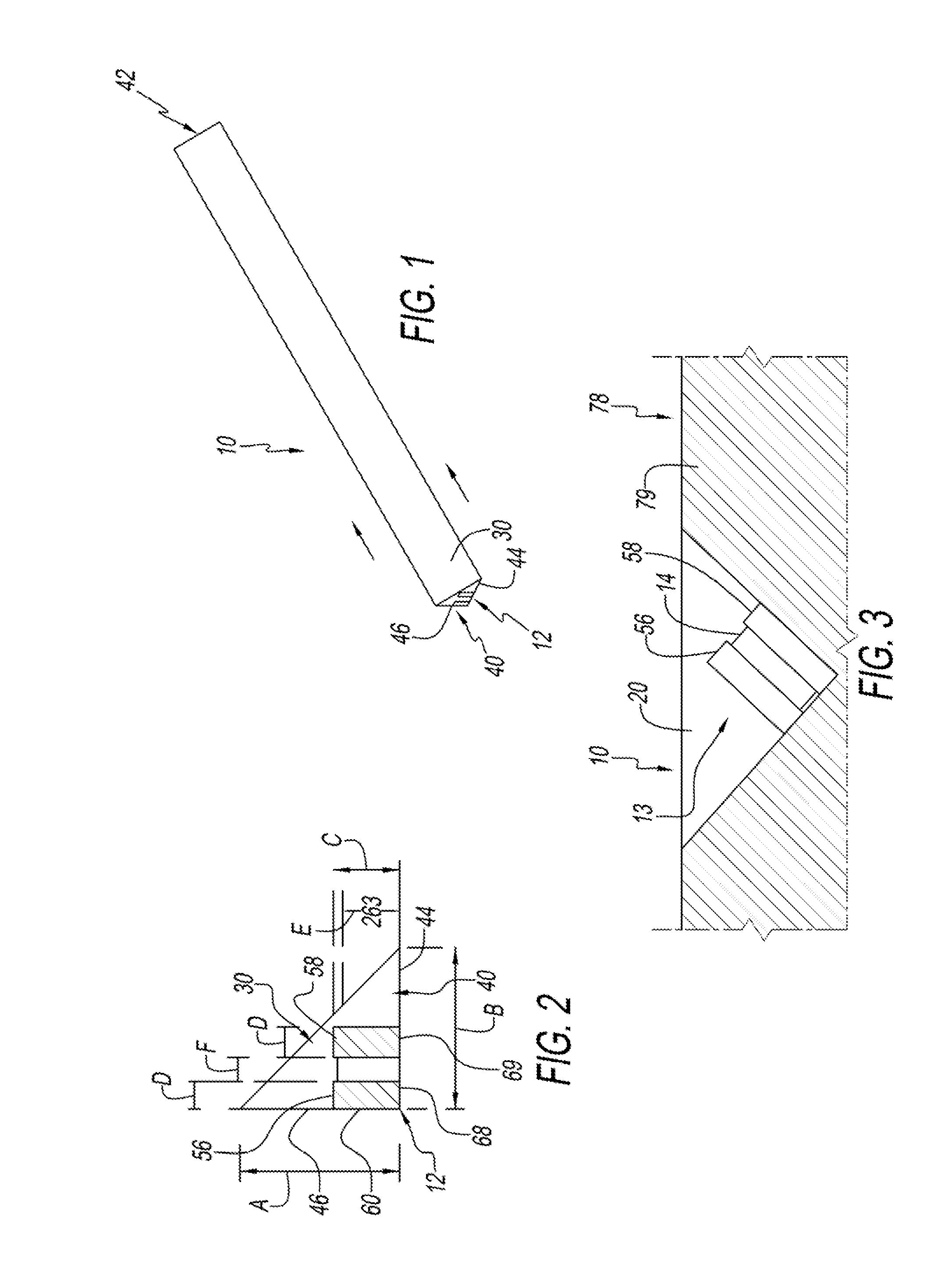
The present invention involves a stiffener / magnet assembly that is used with a composite body to create a mold insert. This results in a relatively rigid mold insert that has good product release features. The use of the stiffener / magnet assembly provides a desirable rigidity while maintaining good product release features.

Problems solved by technology

One disadvantage of the use of the steel form is that the steel in the insert can rust.
Another disadvantage of using a steel insert member is that it does not release well from the concrete, after the concrete is poured into the form and structure and allowed to harden into the end product structure.
In such a case, extra labor is required to separate the steel insert from the concrete structure that was created.
During this separation, the surface of the concrete structure may become marred because chunks of concrete might be adhered to the steel chamfer and thereby form away from the formed structure.

Method used


Image

  • Rigid composite structure for magnetic coupler
  • Rigid composite structure for magnetic coupler
  • Rigid composite structure for magnetic coupler

Examples


third embodiment

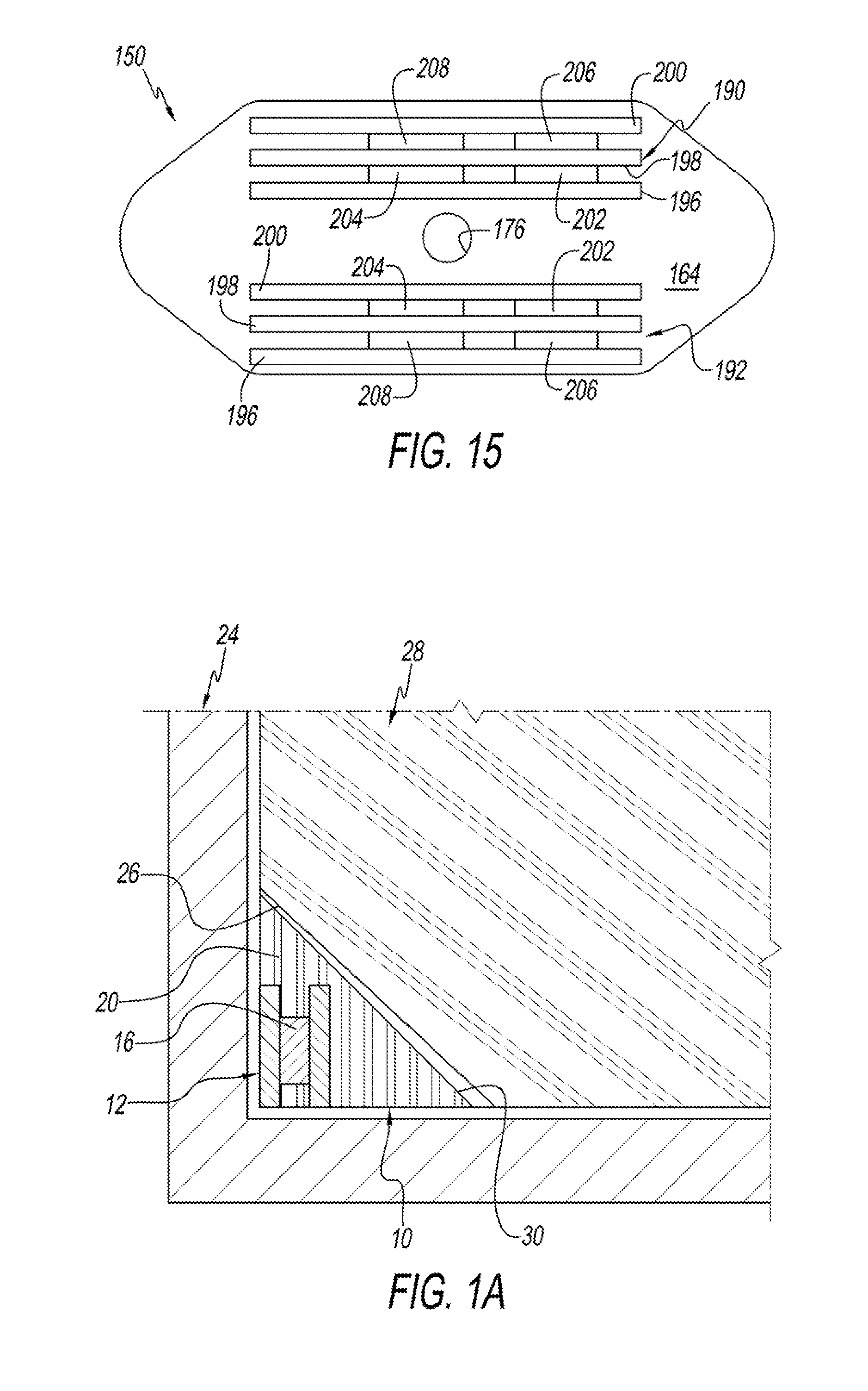
[0089]The third embodiment insert 150 is shown in FIGS. 13-15 as including a body portion 152 that is preferably made from a composite material such as urethane or rubber. Preferably, the urethane or rubber is a relatively rigid compound and has a hardness of somewhere close to or near 90 shore A.

[0090]The body portion 152 of the third mold insert 150 includes a frustoconical perimetral surface 156 that is designed to be frustoconical to promote easy release of the mold insert 150 both from the mold in which it is created, and the mold in which it is used to form a product, such as the pre-cast concrete slab staircase, etc.

[0091]The particular shape of the third embodiment insert 150 is such that it has a first triangular end portion 157, a second triangular end portion 158 and a rectangular middle portion 160 that is disposed between a first and second triangular end portions 157, 158.

[0092]Mold insert 150 further includes a generally planar bottom portion 164 that serves as the mo...

fourth embodiment

[0097]A fourth embodiment mold insert 218 is shown in FIGS. 16-18. The fourth mold insert 218 has a significant number of similarities with second and third mold inserts 100, 150. The primary differences are the fourth mold insert 218 has a different size and shape than the other two mold inserts 100, 150. Additionally, the fourth mold insert 218 lacks a central aperture (that could be added if desired), and also lacks the two-level platform of the mold inserts 100. 150 shown above.

[0098]The fourth embodiment mold insert 218 includes a frustoconical, perimetral surface 220, a one-level, planar top surface 222 and a planar bottom mold engaging surface 224. First and second upstanding posts 226, 228 rise upwardly from the planar top surface 222, and are employed to form blind cavities as features in the product, such as the concrete structure with which the mold insert 218 was employed.

[0099]A first and second stiffener / magnet assembly 232, 234 are disposed in the body portion 236 of ...

embodiment 150

[0100]The first and second stiffener members 232, 234 are constructed generally similarly to the mold stiffener members 124, 126 shown in connection with the mold insert of FIG. 11 and the first and second stiffener / magnet assemblies 190, 192 shown in connection with the third mold insert embodiment 150 shown in FIGS. 14.


PUM


Abstract

A composite member is provided for use with a mold for creating a feature in a product formed in the mold. The composite member includes a bend resistant first stiffener member and at least a first and a second magnet member. The first and second magnet member are configured for forming a magnetic current for magnetically coupling the composite member to the mold. The composite member also includes a composite body portion configured for substantially encasing the stiffener member and the first and second magnet member. The composite body portion includes a product engaging surface configured and positioned for defining a surface of the product formed in the mold.

Description

RELATED APPLICATIONS[0001]This U.S. Non-provisional patent application claims the benefit of and / or priority to Kegeris, U.S. provisional patent application Ser. No. 62 / 027,954 filed 23 Jul. 2014, the entire contents of which is specifically incorporated herein by reference.TECHNICAL FIELD OF THE INVENTION[0002]The present invention relates to construction devices and more particularly to a device used in the manufacture of concrete items, such as pre-cast concrete items.BACKGROUND OF THE INVENTION[0003]Concrete is an ancient building material that has been used for centuries to construct a variety of structures including buildings, roads, sidewalks, parking garages, walls, basements, and surprisingly even boats.[0004]The four primary ingredients of concrete include water, Portland cement, aggregates and admixtures. The four ingredients are mixed together and placed in a flowable form. The flowable concrete is then given its final shape by pouring it into a “form” that serves the sa...

Claims


Application Information

Patent Timeline
IPC IPC(8): B28B7/00B28B7/06
CPCB28B7/002B28B7/06B28B7/0085B28B7/348
Inventor KEGERIS, THEODORE, L
Owner KEGERIS THEODORE L
Learn More