Air guiding device, vehicle and method for operating an air guiding device

a technology of air guiding and air suspension, which is applied in the direction of vehicle body, superstructure, monocoque construction, etc., can solve the problems of disadvantageous aerodynamics, increase the lifting force in and reduce the advantageous lifting in the region of the rear axle of the vehicle, so as to improve the driving performance of the vehicle. , the effect of reducing the lifting force in the rear axle region is significan

Active Publication Date: 2016-01-28
DR ING H C F PORSCHE AG
View PDF4 Cites 12 Cited by
  • Summary
  • Abstract
  • Description
  • Claims
  • Application Information

AI Technical Summary

Benefits of technology

[0015]The first and the second air guiding device may be pivoted into a substantially horizontal position above the contour profile of the hatchback in a first operative position of the air guiding device. The horizontal position of the first and second air guiding elements advantageously achieves as high a shape of the rear as possible, with the rear shape sloping down only minimally, if at all. The hatchback vehicle therefore can be transferred in terms of flow during driving into an aerodynamically significantly more favorable fast back vehicle or high back vehicle (similar to a station wagon). In the first operative position, the aerodynamic drag and the lift in the region of the rear axle of the vehicle advantageously are reduced significantly.
[0016]In a second operative position of the air guiding device, the first air guiding element is pivoted into the horizontal position and the second air guiding element is pivoted into a setting position set beyond the horizontal position. The additionally set second air guiding element advantageously causes a force that is opposed to the lifting force and presses the vehicle in the region of the rear axle toward the road surface to improve traction of the rear wheels. The driving performances of the vehicle can therefore be improved considerably. This is of great interest in particular for sports cars.

Problems solved by technology

Air flowing over the body of a hatchback vehicle is directed down in the rear region and therefore results in a relatively high aerodynamic drag and in an increased lifting force in the region of the rear axle.
However, during slow travel or when the vehicle is at a standstill, the air guiding device is moved into an inconspicuous inoperative position, in which the lines and the esthetics of the vehicle are not affected adversely by the air guiding device.
This short construction depth permits simple pivoting away of the air guiding device into the inoperative position, but is disadvantageous aerodynamically.

Method used


Image

  • Air guiding device, vehicle and method for operating an air guiding device
  • Air guiding device, vehicle and method for operating an air guiding device

Examples


Embodiment Construction

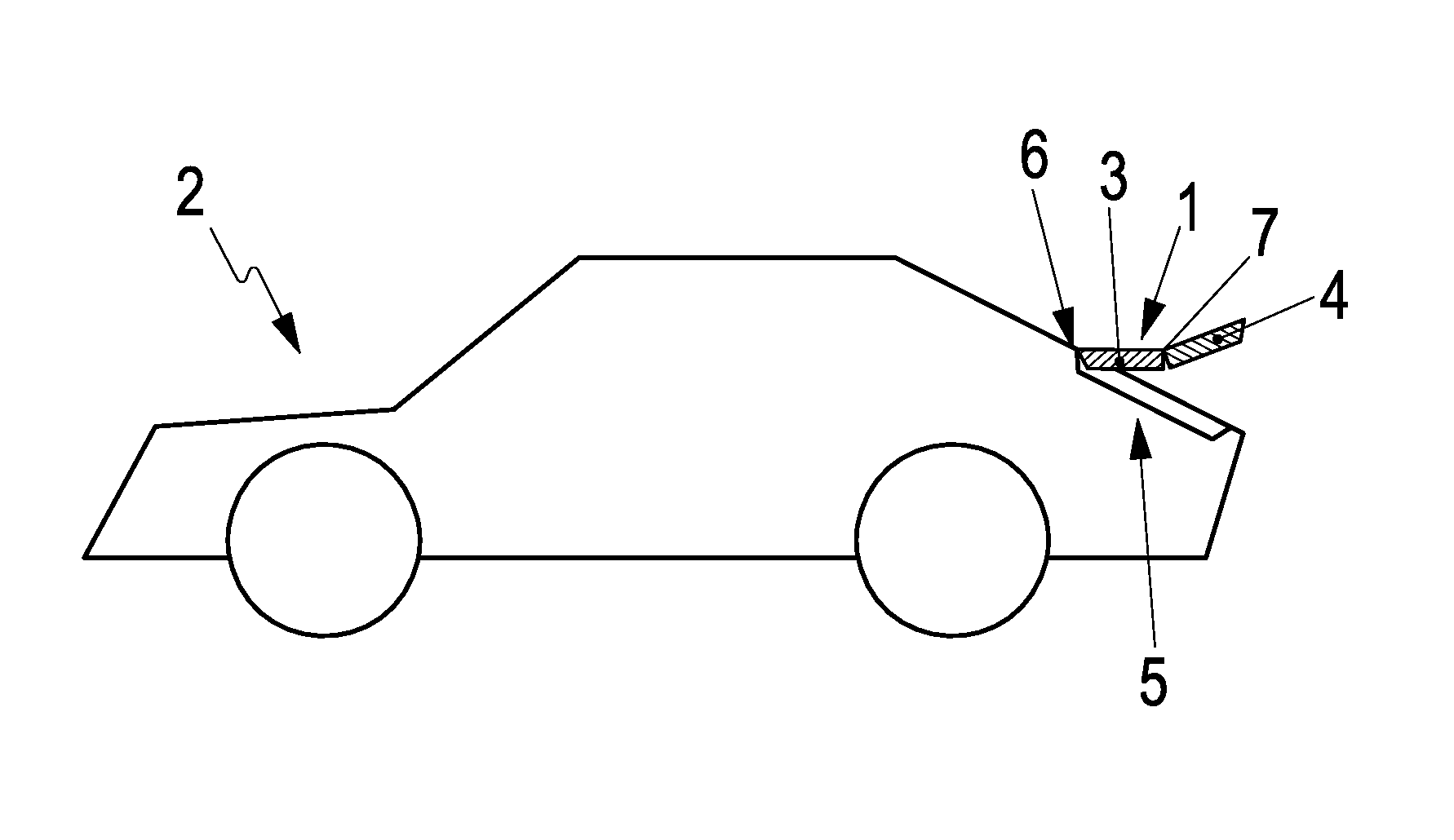
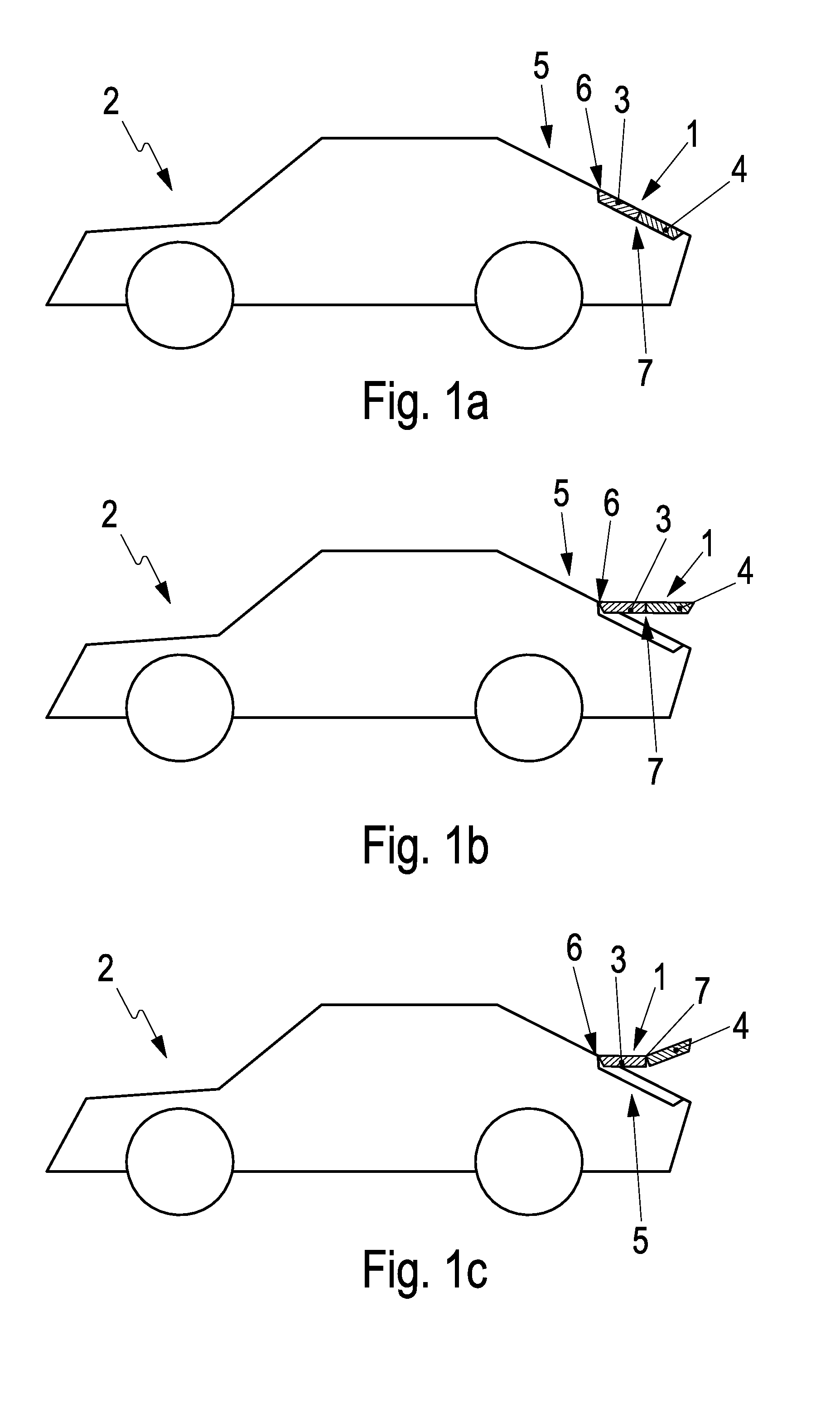
[0024]FIG. 1a is a schematic side view of an air guiding device 1 of a vehicle 2. The vehicle 2 has a rear hatchback in the region of the air guiding device 1.

[0025]The air guiding device 1 is of two-part design and accordingly has a first air guiding element 3 and a second air guiding element 4 that is separate from the first air guiding element 3. The front end of the first air guiding element 3 is fastened pivotably to the rear of the vehicle via a first hinge mechanism 6. The front end of the second air guiding element 4 is fastened pivotably to the rear end of the first air guiding element 3 by means of a second hinge mechanism 7. The first and second air guiding elements 3 and 4 are flat wing elements for deflecting or diverting the airflow caused by the movement of the vehicle 2 (relative wind) over the body of the vehicle 2.

[0026]The first air guiding element 3 is pivotable by the first hinge mechanism 6 relative to the rear 5 about a first axis of rotation that runs paralle...


PUM


Abstract

An air guiding device for a vehicle has a first air guiding element and a second air guiding element. A first hinge mechanism connects the first air guiding element hingedly to a rear of the vehicle, and a second hinge mechanism connects the second air guiding element hingedly to the first air guiding element.

Description

CROSS REFERENCE TO RELATED APPLICATION[0001]This application claims priority under 35 USC 119 to German Patent Appl. No. 10 2014 110 394.7 filed on Jul. 23, 2014, the entire disclosure of which is incorporated herein by reference.BACKGROUND[0002]1. Field of the Invention[0003]The invention relates to an air guiding device for a vehicle.[0004]2. Description of the Related Art[0005]Air flowing over the body of a hatchback vehicle is directed down in the rear region and therefore results in a relatively high aerodynamic drag and in an increased lifting force in the region of the rear axle.[0006]Air guiding devices, such as wings or spoilers, are used in the prior art to influence the air flow of sports cars in an advantageous manner and to improve the aerodynamics of the vehicle body. Some air guiding devices are motorized to move or deploy into an operative position only when required, i.e. when a certain speed is exceeded. However, during slow travel or when the vehicle is at a stand...

Claims


Application Information

Patent Timeline
Patent Type & Authority Applications(United States)
IPC IPC(8): B62D35/00
CPCB62D35/007B62D25/20B60K1/04B60K11/02B60K2001/005B60K2001/0438B60L58/26B60L50/66Y02T10/70
Inventor WOLF, THOMAS
Owner DR ING H C F PORSCHE AG
Why Eureka
Try Eureka