Controlling combustion noise of diesel fuel

a technology of combustion noise and diesel fuel, which is applied in the direction of electrical control, process and machine control, instruments, etc., can solve the problem of not disclosing

Active Publication Date: 2016-01-28
HYUNDAI MOTOR CO LTD
View PDF7 Cites 5 Cited by
  • Summary
  • Abstract
  • Description
  • Claims
  • Application Information

AI Technical Summary

Benefits of technology

The patent describes a method and system for controlling the combustion noise of diesel fuel in a vehicle engine. The method involves setting target values for crank angle and combustion noise index, calculating the difference between the current conditions and the target values, and calibrating the pilot fuel amount injected into the engine to achieve the desired noise level. The system includes a detector, calculator, and data storage for storing the target values and a controller for transmitting signals to a main fuel injection unit to calibrate the pilot fuel amount and achieve the desired noise level. The technical effect of this method and system is to reduce combustion noise in diesel engines and improve fuel efficiency.

Problems solved by technology

However, the method is giving place to closed loop control to calibrate emission, drivability and instability of engine operations resulting from variations in hardware.
However, the above disclosure is effective in that the reduction rate for a pressure increase slope of a combustion pressure (cylinder pressure) in a combustion chamber is surged by splitting the total amount of fuel to be injected into an engine into a pilot injection amount and a split injection amount, but has its limitations in that it does not disclose a technical idea, like that of the present disclosure, in which the concept of a combustion noise index is employed to control a pilot fuel injection amount by comparing with the preset target values of injection parameters.

Method used


Image

  • Controlling combustion noise of diesel fuel
  • Controlling combustion noise of diesel fuel
  • Controlling combustion noise of diesel fuel

Examples


Embodiment Construction

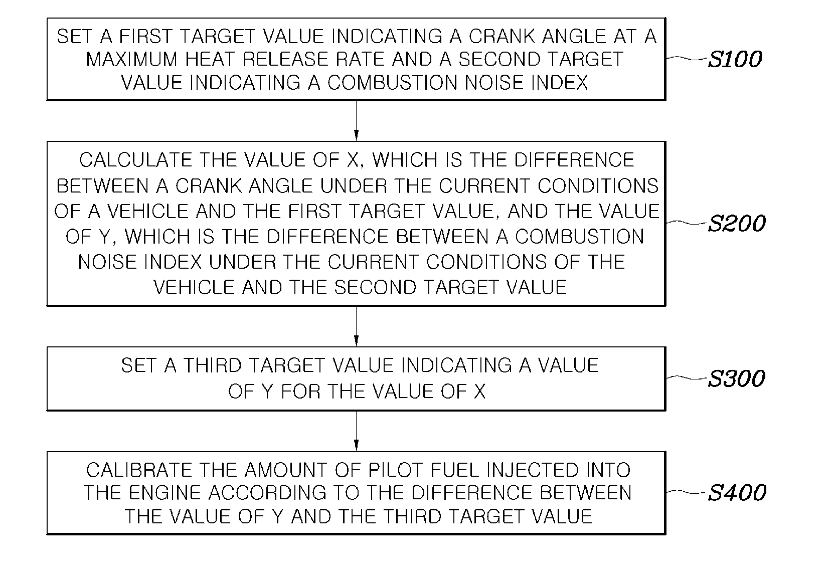
[0029]The techniques described in the present disclosure have been made keeping in mind the above-mentioned shortcomings of the prior art. The object of the present disclosure is to provide a method and a system for controlling a combustion noise of diesel vehicles to improve fuel efficiency and reduce a combustion noise by employing the concept of a combustion noise index, which is closely related with a combustion noise of diesel vehicles, and calibrating a main injection timing, as well as controlling injection parameters of fuel injected into an engine with the use of the difference between a preset combustion noise index and a measured combustion noise index.

[0030]From here on, a preferred embodiment of a method and a system for controlling a combustion noise of diesel fuel is described with reference to the accompanying figures.

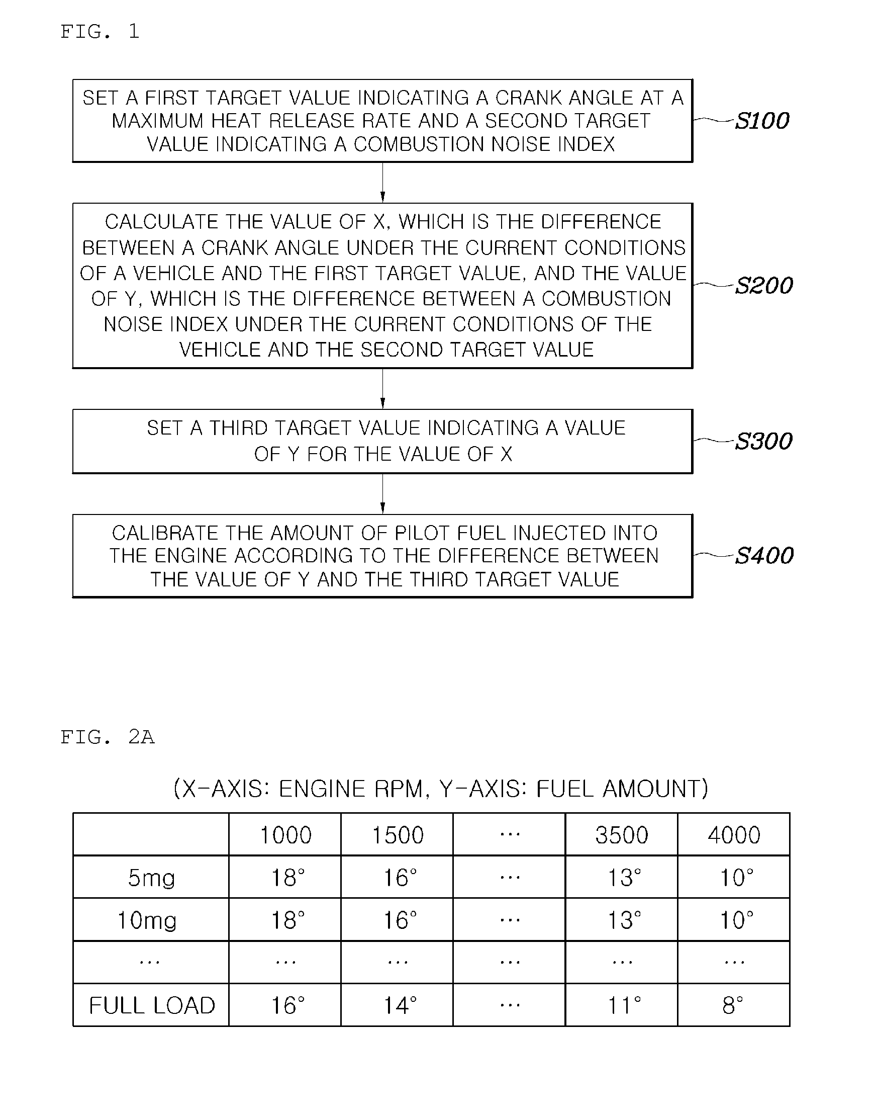
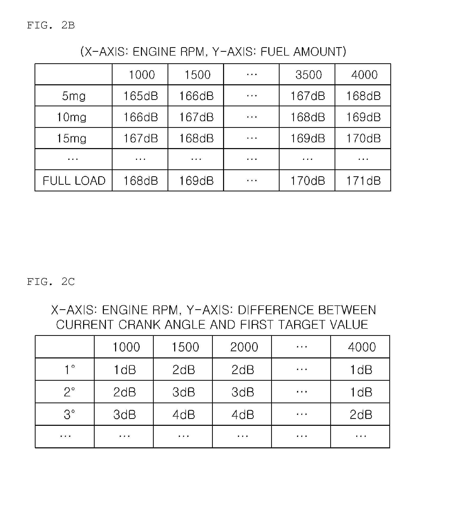
[0031]FIG. 1 is an overall flow chart for a method of controlling a combustion noise of diesel fuel, which is part of the present disclosure, and FIG. ...


PUM


Abstract

Disclosed herein is a method of controlling combustion noise of diesel fuel. The method includes steps of setting a first target value indicating a crank angle at a maximum heat release rate and a second target value indicating a combustion noise index; calculating the value of X, which is the difference between a crank angle under the current conditions of a vehicle and the first target value and calculating the value of Y, which is the difference between a combustion noise index under the current conditions of the vehicle and the second target value; setting a third target value indicating a value of Y for the value of X, and calibrating the amount of pilot fuel injected into an engine according to the difference between the value of Y and the third target value.

Description

CROSS REFERENCE TO RELATED APPLICATION[0001]The present application claims priority to Korean Patent Application No. 10-2014-0095971, filed Jul. 28, 2014, the entire contents of which is incorporated herein for all purposes by this reference.BACKGROUND[0002]1. Field of the Application[0003]The present disclosure relates generally to a method and a system for controlling a combustion noise of diesel fuel and, more particularly, to a method and a system for controlling a combustion noise of diesel fuel to reduce a combustion noise of a diesel engine and improve fuel efficiency thereof by controlling injection parameters for the engine and a cylinder pressure level and adjusting a main injection timing with the use of a crank angle at a predetermined maximum heat release rate and a combustion noise index.[0004]2. Description of the Related Art[0005]As well known in the art, in the control of an internal combustion engine, a fuel injection mode changes in accordance with the operation c...

Claims


Application Information

Patent Timeline
Patent Type & Authority Applications(United States)
IPC IPC(8): F02D41/40F02D41/00F02D41/14
CPCF02D41/403F02D41/0097F02D41/1497F02D41/1486F02D41/14F02D41/009F02D35/023F02D35/028F02D2041/288F02D2200/025Y02T10/40
Inventor JUNG, IN, SOO
Owner HYUNDAI MOTOR CO LTD
Why Eureka
Try Eureka