
Controller for vehicle and method for controlling vehicle

a technology for controlling devices and vehicles, applied in the direction of electrical control, machine/engine, exhaust treatment electric control, etc., can solve the problems of deterioration of catalysts, affecting so as to improve the efficiency of catalysts and reduce the temperature of catalysts, the effect of increasing the amount of fuel in the air-fuel mixture and drawn into the catalytic devi

Active Publication Date: 2020-07-30
TOYOTA JIDOSHA KK
View PDF0 Cites 0 Cited by
  • Summary
  • Abstract
  • Description
  • Claims
  • Application Information

AI Technical Summary

Benefits of technology

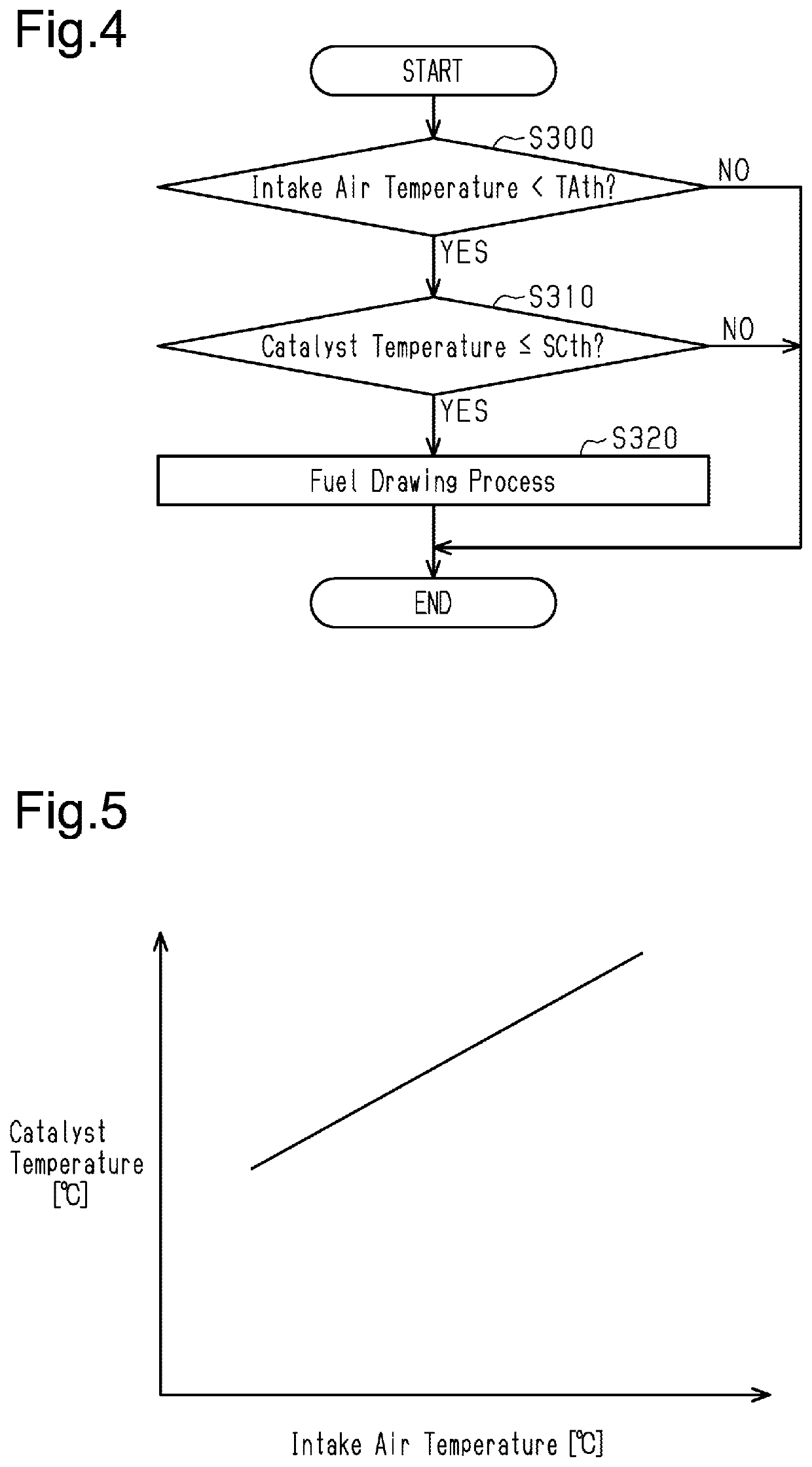
The invention relates to a method of controlling the air-fuel mixture in a vehicle during the fuel drawing process to prevent overheating of the catalytic device and reduce fuel consumption. The method involves controlling the air-fuel ratio based on the intake air temperature, reducing the amount of fuel contained in the air-fuel mixture when the intake air temperature is high, and increasing the amount of fuel when the intake air temperature is low. This ensures that the temperature of the catalytic device does not increase excessively, reducing the risk of damage to the device. The method can also enhance heat generation and improve combustion of particulate matter.

Problems solved by technology

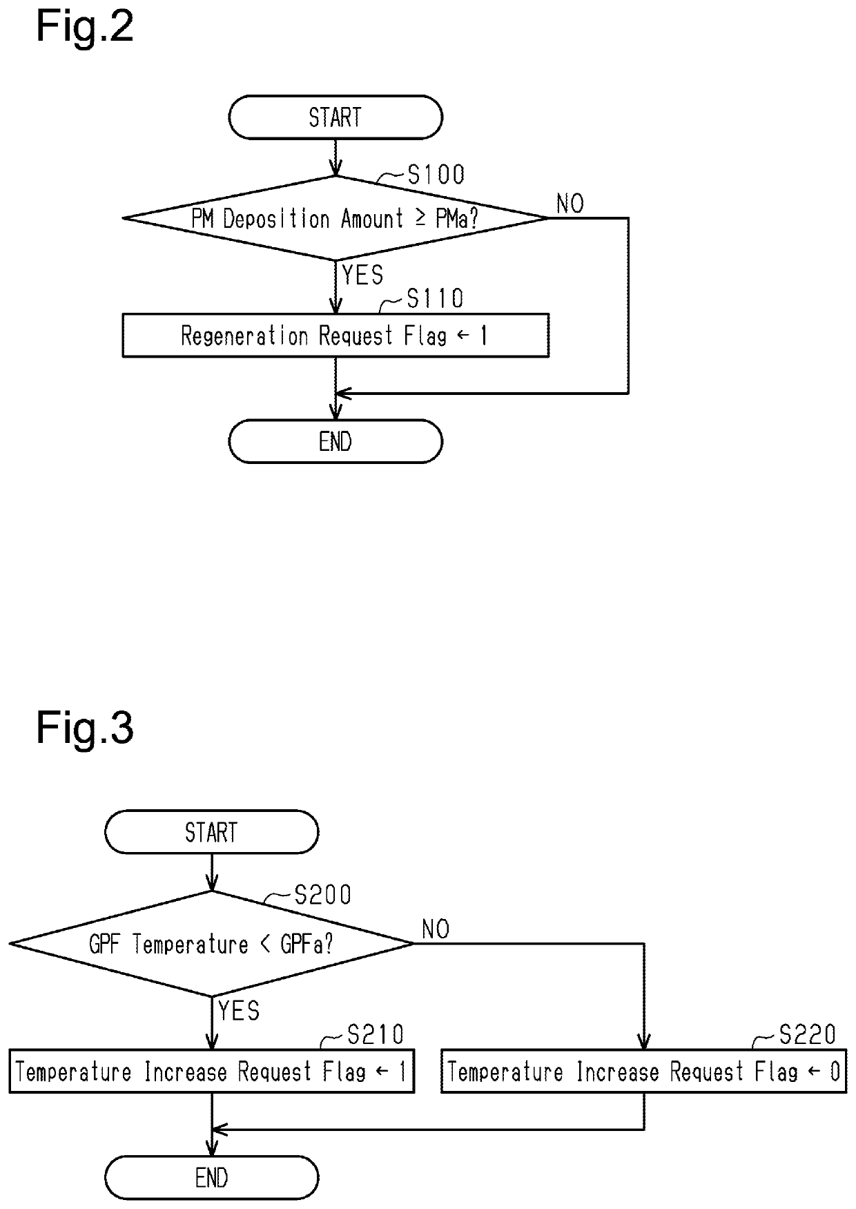
The collected PM gradually deposits on the filter and may eventually clog the filter.
In the fuel drawing process, if heat is overly generated in the catalytic device, the temperature of the catalytic device may excessively increase and cause deterioration of the catalyst.
This increases the temperature of the catalytic device.
That is, when the intake air temperature is relatively high and thus the temperature of the catalytic device is likely to increase, the amount of fuel that is burned in the catalytic device is reduced so that heat generation is limited.
In the configuration described above, when the intake air temperature is greater than or equal to the specified temperature and thus the catalytic device may be overly heated, the fuel drawing process is not executed.
Thus, overheat of the catalytic device is further accurately limited.
This results in lost time during which particulate matter could be burned.

Method used


Image

  • Controller for vehicle and method for controlling vehicle
  • Controller for vehicle and method for controlling vehicle
  • Controller for vehicle and method for controlling vehicle

Examples


Embodiment Construction

[0036]This description provides a comprehensive understanding of the methods, apparatuses, and / or systems described. Modifications and equivalents of the methods, apparatuses, and / or systems described are apparent to one of ordinary skill in the art. Sequences of operations are exemplary, and may be changed as apparent to one of ordinary skill in the art, with the exception of operations necessarily occurring in a certain order. Descriptions of functions and constructions that are well known to one of ordinary skill in the art may be omitted.

[0037]Exemplary embodiments may have different forms, and are not limited to the examples described. However, the examples described are thorough and complete, and convey the full scope of the disclosure to one of ordinary skill in the art.

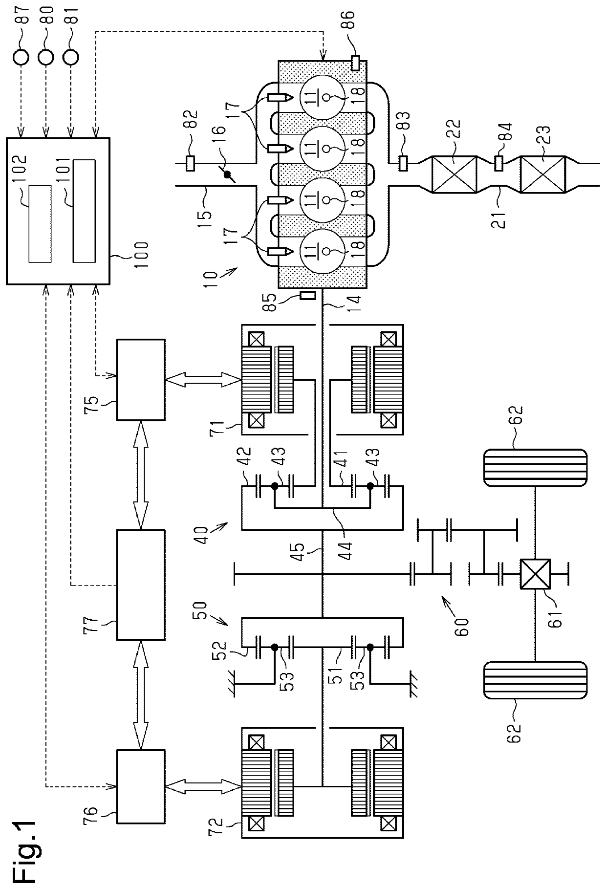
[0038]An embodiment of a controller for a vehicle according to the present disclosure will now be described with reference to FIGS. 1 to 8. The controller of the present embodiment is installed on a hybrid veh...


PUM


Abstract

A controller for a vehicle is provided. Temperature increasing control executed by a temperature increasing control unit executes a fuel drawing process to generate heat in a catalytic device and transfer the generated heat to a downstream side via gas flowing through the exhaust passage. The fuel drawing process performs fuel injection as a crankshaft is rotated when combustion in a cylinder is stopped to draw an air-fuel mixture containing unburned fuel into the catalytic device. An obtainment unit obtains an intake air temperature. A temperature increasing control unit controls an air-fuel ratio of the air-fuel mixture in the fuel drawing process based on the intake air temperature so that when the intake air temperature is relatively high, the air-fuel ratio of the air-fuel mixture becomes a leaner value than when the intake air temperature is relatively low.

Description

BACKGROUND1. Field[0001]The present disclosure relates to a controller for a vehicle and a method for controlling a vehicle. The vehicle includes an internal combustion engine having an exhaust passage provided with a catalytic device.2. Description of Related Art[0002]US Patent Application Publication No. 2014 / 0041362 describes an exhaust purifier of an internal combustion engine. The exhaust purifier includes a filter configured to collect particulate matter from exhaust and a catalytic device disposed on a portion of the exhaust passage upstream of the filter. In the description hereafter, particulate matter is referred to as PM.[0003]In such an internal combustion engine, the filter collects PM produced in cylinders to limit discharging of PM. The collected PM gradually deposits on the filter and may eventually clog the filter.[0004]In this regard, in the internal combustion engine described in the above document, filter regeneration control that burns PM deposited on the filter...

Claims


Application Information

Patent Timeline
Patent Type & Authority Applications(United States)
IPC IPC(8): F02D41/30
CPCF02D2200/0414F02D41/30F02D41/029F02D41/024F01N3/023F01N3/2006F01N9/002F02D41/025F02D41/042F01N13/009F01N2260/04F01N3/101F01N3/021F01N3/0253F01N2430/06F01N2430/08F01N2900/08Y02T10/12
Inventor IKEDA, YUTONOSE, YUKIMYOJO, KEIICHI
Owner TOYOTA JIDOSHA KK
Learn More