Internal rotation type biomass pyrolysis furnace

A biomass pyrolysis and internal rotation technology, applied in the field of pyrolysis furnaces, can solve the problems of low pyrolysis efficiency, affecting the quality of biomass pyrolysis, low output of pyrolysis oil and pyrolysis gas, etc. Surface area, improved heat generation effect, and improved yield effect

Active Publication Date: 2019-05-24
HUNAN UNIV OF HUMANITIES SCI & TECH
View PDF17 Cites 5 Cited by
  • Summary
  • Abstract
  • Description
  • Claims
  • Application Information

AI Technical Summary

Problems solved by technology

The biomass in the existing pyrolysis furnace is fed into the furnace body and piled up into blocks. On the one hand, the efficiency of biomass pyrolysis is reduced, and the biomass is heated unevenly, which seriously affects the quality of biomass pyrolysis. The output of pyrolysis oil and pyrolysis gas is low. On the other hand, some of the high molecular substances soften and become sticky when exposed to high temperature, and adhere to the inner wall of the furnace, or wrap on the surface of other biomass, resulting in low pyrolysis efficiency and formation of biomass on the inner wall of the furnace. The thermal effect becomes worse, and the pyrolysis temperature of some high-ignition biomass cannot be reached. In view of this, we propose an internal rotation biomass pyrolysis furnace

Method used


Image

  • Internal rotation type biomass pyrolysis furnace
  • Internal rotation type biomass pyrolysis furnace
  • Internal rotation type biomass pyrolysis furnace

Examples


Embodiment Construction

[0022] The following will clearly and completely describe the technical solutions in the embodiments of the present invention with reference to the accompanying drawings in the embodiments of the present invention. Obviously, the described embodiments are only some, not all, embodiments of the present invention. Based on the embodiments of the present invention, all other embodiments obtained by persons of ordinary skill in the art without creative efforts fall within the protection scope of the present invention.

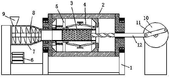
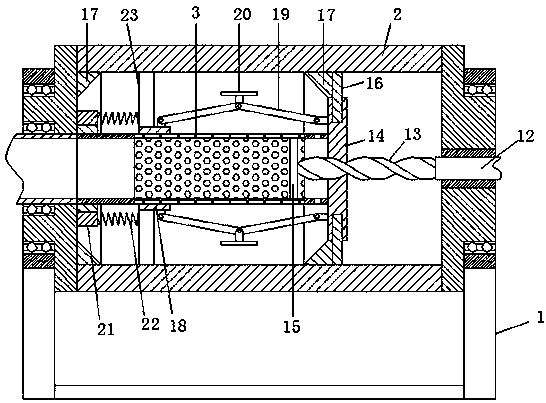
[0023] see Figure 1-6 , the present invention provides a technical solution: an internal rotation biomass pyrolysis furnace includes a horizontal furnace body 2, the two ends of the furnace body 2 are installed on the support 1, and the left end of the furnace body 2 is connected to the feeding device. Inside the furnace body 2, there is an inner cylinder 3 coaxially placed horizontally. Both ends of the inner cylinder 3 are connected to the inner wall of the furn...


PUM


Abstract

The invention relates to the field of pyrolysis furnaces, in particular to an internal rotation type biomass pyrolysis furnace, which comprises a transversely-arranged furnace body, wherein two ends of the furnace body are mounted on a support; the left end of the furnace body is connected with a feeding device; an inner cylinder is transversely arranged inside the furnace body in a coaxial manner; two ends of the inner cylinder are connected to the inner wall of the furnace body through fixing shafts in a rotary manner; the right end of the inner cylinder is connected with a driving mechanism; the left end of the inner cylinder is connected with a feeding port of the feeding device; a wall scraping mechanism is connected to the outside of the inner cylinder in a sleeved manner; the wall scraping mechanism is used for scraping the biomass adhered to the inner wall of the furnace body and simultaneously cooperating with the inner cylinder for granulating; and a shock wall mechanism is arranged between the wall scraping mechanism and the right end of the inner cylinder for crushing the biomass and vibrating the biomass adhered to the inner wall of the furnace body. According to the internal rotation type biomass pyrolysis furnace, granulation is carried out through the inner cylinder, and adhesion of biomass to the inner wall of the furnace body is avoided through the wall shaking mechanism and the wall scraping mechanism, and thus the heat generation effect of the inner wall of the furnace body is improved, and the heat inside the furnace body is uniform, so that the biomasspyrolysis efficiency and the yield of pyrolysis gas and pyrolysis oil are improved.

Description

technical field [0001] The invention relates to the field of pyrolysis furnaces, in particular to an internal rotation type biomass pyrolysis furnace. Background technique [0002] Biomass refers to various organisms produced through photosynthesis using the atmosphere, water, land, etc., that is, all living organic substances that can grow are collectively referred to as biomass. It includes plants, animals and microorganisms. Broad concept: Biomass includes all plants, microorganisms, animals that feed on plants and microorganisms, and their wastes. Representative biomass is crops, crop waste, wood, wood waste and animal manure. Narrow concept: Biomass mainly refers to lignocellulose such as straw and trees other than grain and fruit in the process of agricultural and forestry production, leftovers of agricultural product processing industry, agricultural and forestry waste, and poultry manure and waste in the process of animal husbandry production, etc. substance. Fea...

Claims


Application Information

Patent Timeline
Patent Type & Authority Applications(China)
IPC IPC(8): C10B53/00C10B57/00B01J2/12
Inventor 刘海力
Owner HUNAN UNIV OF HUMANITIES SCI & TECH
Why Eureka
Try Eureka