Electric rotating machine with laterally magnetized magnets

a technology of electric rotating machines and magnets, which is applied in the direction of magnetic circuit rotating parts, magnetic circuits characterised by magnetic materials, and magnetic circuits. it can solve the problems of poor thermal conductivity of the magnets and higher mass of the inner stator, so as to achieve better thermal conductivity, improve the efficiency of electric rotating machines, and improve the effect of cost-effectiveness

Inactive Publication Date: 2016-10-06
SIEMENS AG
View PDF9 Cites 5 Cited by
  • Summary
  • Abstract
  • Description
  • Claims
  • Application Information

AI Technical Summary

Benefits of technology

[0017]According to another advantageous feature of the present invention, the permanent magnets can have a section which faces away from the internal air gap and essentially follows a preferred magnetic direction. It is significant here that no additional reflux material needs to be provided inside the rotor as a result of the lateral magnetization of the permanent magnets shaped in this way as both magnetic pole formation and magnetic field guidance occur in the permanent magnet.
[0018]According to another advantageous feature of the present invention, the rotor can include a support element which is made of a non-magnetic material and has a plurality of recesses in each of which a magnetically soft segment can be arranged. A non-magnetic material cannot usually be influenced by a magnetic field. A plurality of magnetically soft segments is embedded in the support element. As the inner stator of the electric rotating machine also has a plurality of permanent magnets, a permanently excited three-phase synchronous machine can be provided in which the permanent magnets are not moved during the operation of the electric rotating machine. Thus, heat generated during operation of the electric rotating machine can be dissipated from the permanent magnets with greater ease than in the case of electric rotating machines in which the permanent magnets are arranged in the rotor.
[0019]According to another advantageous feature of the present invention, the permanent magnets of the inner stator can be made of a ferrite. Ferrites are ferrimagnetic ceramic materials which have poor electric conductivity or are non-conductive. Standard materials are, for example, strontium ferrites, barium ferrites and cobalt ferrites. Such permanent magnets are more cost-effective compared with rare earth magnets.
[0020]According to another advantageous feature of the present invention, the electric rotating machine can have a first cooling device for cooling the permanent magnets of the inner stator. Heat generated during the operation of the electric machine can thus be reliably dissipated from the permanent magnets of the inner stator as a coolant. In this way, it is possible to prevent the permanent magnets from being demagnetized. It is thus possible to use magnets with lower coercive field strength. This in turn means that permanent magnets with a lower proportion of rare earth elements can be used. In this way, the remanence can be increased and the costs reduced.
[0021]According to another advantageous feature of the present invention, the electric machine can have a second cooling device for cooling the outer stator. The second cooling device can prevent the windings of the outer stator from overheating and thus possibly being damaged during operation of the electric machine. In this way the reliable operation of the electric machine is made possible.
[0022]According to another advantageous feature of the present invention, the first cooling device and / or the second cooling device can have a plurality of cooling pipes, through which a coolant flows. Water or a water-glycol mixture, for example, can be used as a coolant. Corresponding cooling pipes can be produced easily and inexpensively. In one embodiment the cooling pipes are arranged in a laminated core of the inner stator and / or in an iron core of the outer stator. For example, the cooling pipes of the first cooling device and / or the second cooling device can be provided through corresponding holes which are inserted into the respective iron core. Such cooling pipes are easy and inexpensive to produce.

Problems solved by technology

As a result, the inner stator has a higher mass, also requires the material iron and thereby also has poorer thermal conductivity to the magnets compared with aluminum or copper.

Method used


Image

  • Electric rotating machine with laterally magnetized magnets
  • Electric rotating machine with laterally magnetized magnets
  • Electric rotating machine with laterally magnetized magnets

Examples


Embodiment Construction

[0031]Throughout all the figures, same or corresponding elements may generally be indicated by same reference numerals. These depicted embodiments are to be understood as illustrative of the invention and not as limiting in any way. It should also be understood that the figures are not necessarily to scale and that the embodiments may be illustrated by graphic symbols, phantom lines, diagrammatic representations and fragmentary views. In certain instances, details which are not necessary for an understanding of the present invention or which render other details difficult to perceive may have been omitted.

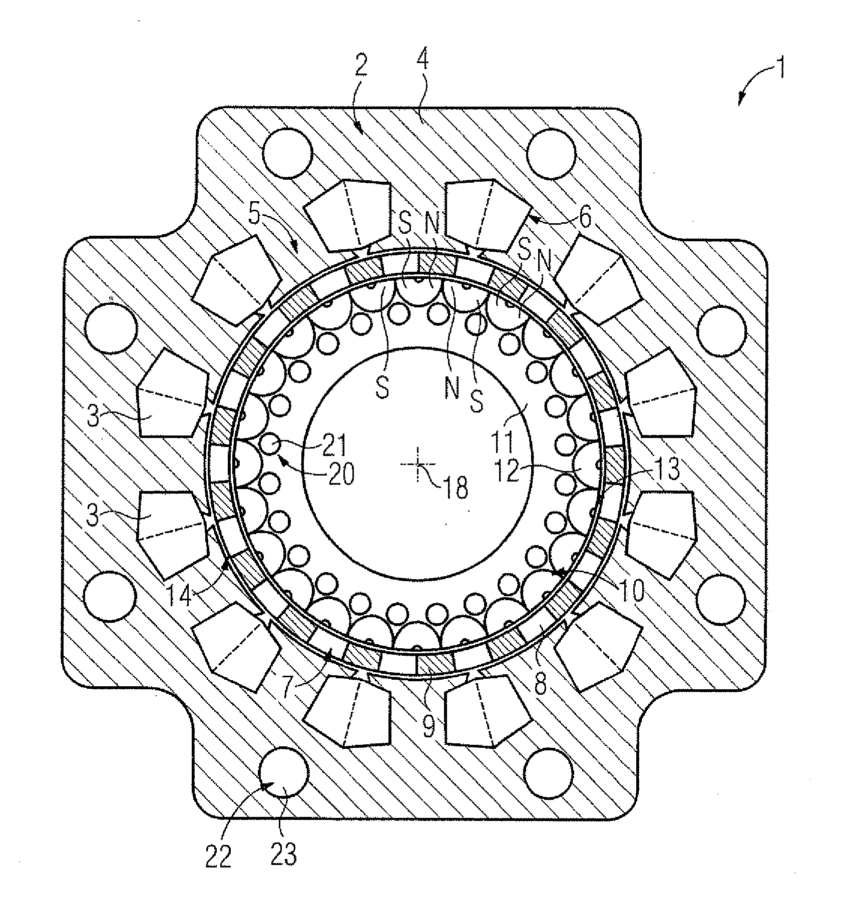
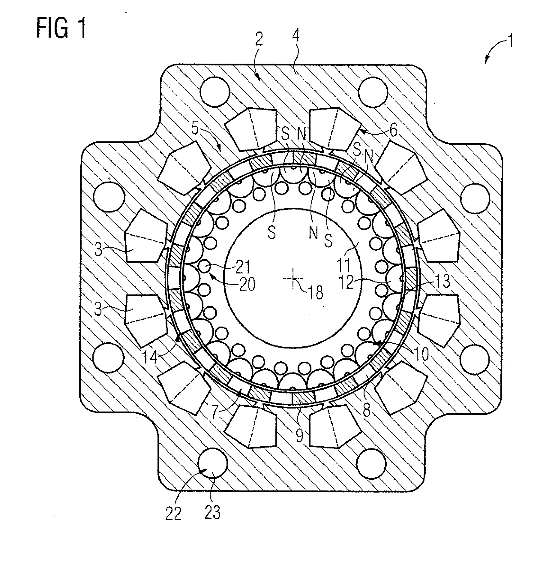
[0032]Turning now to the drawing, and in particular to FIG. 1, there is shown a cross-section of one embodiment of an electric rotating machine according to the present invention, generally designated by reference numeral 1. The electric rotating machine 1 has an outer stator 2, The outer stator 2 has an iron core 4 which has a plurality of teeth 5 with intermediate grooves 6. Corr...


PUM


Abstract

An electric rotating machine includes an outer stator, and an inner stator arranged inside the outer stator in concentric relationship to the outer stator. The inner stator has a plurality of permanent magnets which contain iron-neodymium-boron. A rotor is arranged in concentric relationship to the outer stator and the inner stator between the outer stator and the inner stator. The rotor is configured for movement in relation to the outer stator and the inner stator and defines with the inner stator an internal air gap there between. Each permanent magnet of the inner stator has a north pole and a south pole on a side facing the internal air gap.

Description

CROSS-REFERENCES TO RELATED APPLICATIONS[0001]This application claims the priority of European Patent Application, Serial No. 15162240.4, filed Apr. 1, 2015, pursuant to 35 U.S.C. 119(a)-(d), the disclosure of which is incorporated herein by reference in its entirety as if fully set forth herein.BACKGROUND OF THE INVENTION[0002]The present invention relates to an electric rotating machine with laterally magnetized magnets. The present invention further relates to a wind turbine with a generator which includes such an electric rotating machine, and to a drive for an electrically driven aircraft or an electrically driven vehicle or an electric traction vehicle with such an electric rotating machine.[0003]The following discussion of related art is provided to assist the reader in understanding the advantages of the invention, and is not to be construed as an admission that this related art is prior art to this invention.[0004]Electric machines are, for example, designed as synchronous ...

Claims


Application Information

Patent Timeline
Patent Type & Authority Applications(United States)
IPC IPC(8): H02K1/17H02K1/20H02K1/22B60K1/00H02K5/20H02K9/19H02K16/04F03D9/00H02K1/02H02K3/28
CPCH02K1/17H02K1/02H02K1/20H02K1/22H02K3/28B60K2001/006H02K9/19H02K16/04F03D9/002B60K1/00H02K5/20H02K9/197H02K21/40H02K5/203F03D9/25Y02E10/72
Inventor VOLKMUTH, BENJAMINVOLLMER, ROLF
Owner SIEMENS AG
Why Eureka
Try Eureka