Shock absorber

a technology of shock absorber and shock absorber, which is applied in the direction of shock absorbers, mechanical devices, transportation and packaging, etc., can solve the problems of passenger feeling and degrading achieve the effects of improving the ride quality of the vehicle, suppressing the generation of clunking sounds, and reducing the noise of passengers

Inactive Publication Date: 2016-01-28
KYB CORP
View PDF8 Cites 9 Cited by
  • Summary
  • Abstract
  • Description
  • Claims
  • Application Information

AI Technical Summary

Benefits of technology

[0007]Meanwhile, a clunking sound is generated when the free piston collides with the step portion of the housing. This clunking sound may be transmitted through a vehicle chassis and may be echoed inside the cabin, so that a passenger may feel uncomfortable or unstable, and ride quality of a vehicle may be degraded.
[0008]In view of the aforementioned problems, it is therefore an object of this invention to provide a shock absorber capable of suppressing generation of a clunking sound and improving ride quality of a vehicle.

Problems solved by technology

This clunking sound may be transmitted through a vehicle chassis and may be echoed inside the cabin, so that a passenger may feel uncomfortable or unstable, and ride quality of a vehicle may be degraded.

Method used


Image

  • Shock absorber
  • Shock absorber
  • Shock absorber

Examples


Embodiment Construction

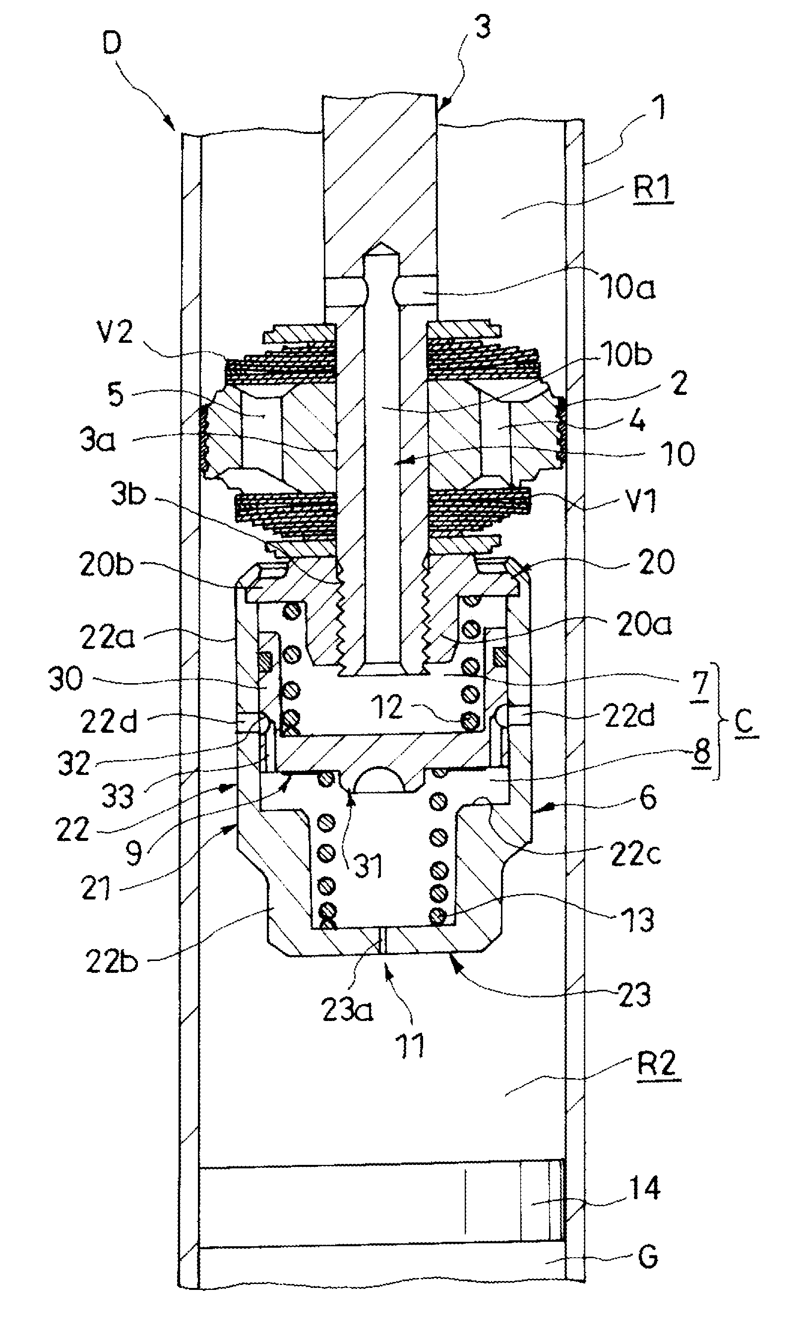
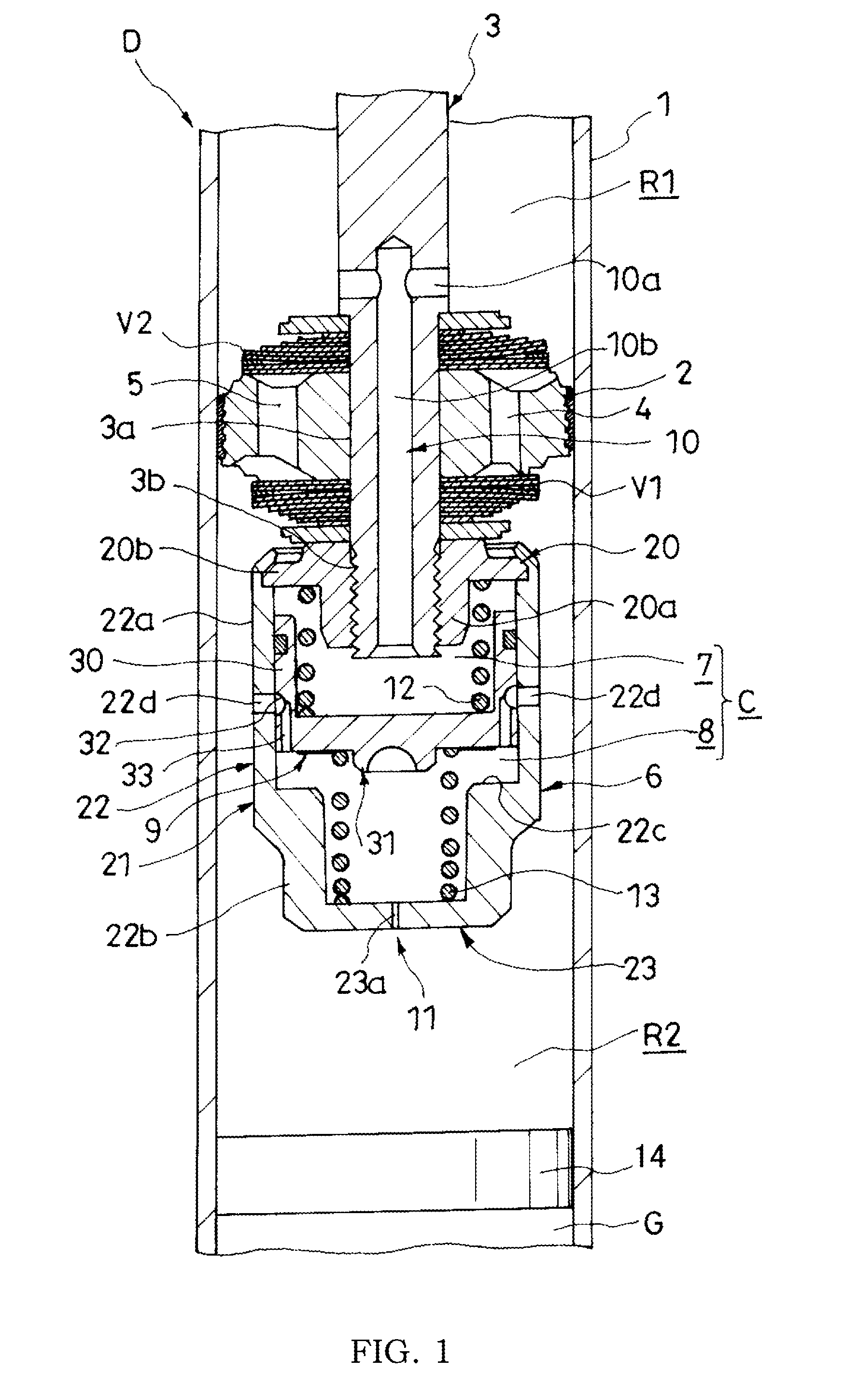
[0013]A description will now be made for a shock absorber according to an embodiment of this invention with reference to FIG. 1.

[0014]Referring to FIG. 1, a shock absorber D comprises a cylinder 1, a piston 2 slidably inserted into the cylinder 1 to partition the cylinder 1 into an expanding-side chamber R1 and a contracting-side chamber R2, damping passages 4 and 5 that cause the expanding-side chamber R1 and the contracting-side chamber R2 to communicate with each other, a housing 6 that forms a pressurizing chamber C, a free piston 9 slidably inserted into the housing 6 to partition the pressurizing chamber C into an expansive pressurizing chamber 7 and a contractive pressurizing chamber 8, an expanding-side passage 10 that causes the expanding-side chamber R1 and the expansive pressurizing chamber 7 to communicate with each other, a contracting-side passage 11 that causes the contracting-side chamber R2 and the contractive pressurizing chamber 8 to communicate with each other, a...


PUM


Abstract

A shock absorber includes expanding-side and contracting-side chambers formed in a cylinder, a housing that forms a pressurizing chamber, a free piston that partitions the pressurizing chamber into an expansive pressurizing chamber communicating with the expanding-side chamber and a contractive pressurizing chamber communicating with the contracting-side chamber, and expanding-side and contracting-side springs that exert biasing forces for suppressing the free piston from being displaced from a neutral position. The contracting-side spring has a non-linear characteristic by which the spring constant increases as it is compressed.

Description

TECHNICAL FIELD[0001]The present invention relates to improvement of a shock absorber.BACKGROUND ART[0002]In JP 2008-215459 A, there is discussed a shock absorber including a cylinder, a piston slidably inserted into the cylinder to partition the cylinder into an expanding-side chamber and a contracting-side chamber, a damping passage that causes the expanding-side chamber and the contracting-side chamber provided in the piston to communicate with each other, a housing provided in a leading end of the piston rod to form a pressurizing chamber, a free piston slidably inserted into the pressurizing chamber to partition the pressurizing chamber into an expansive pressurizing chamber and a contractive pressurizing chamber, a coil spring that biases the free piston, an expanding-side passage that causes the expanding-side chamber and the expansive pressurizing chamber to communicate with each other, and a contracting-side passage that causes the contracting-side chamber and the contracti...

Claims


Application Information

Patent Timeline
Patent Type & Authority Applications(United States)
IPC IPC(8): F16F9/348F16F9/512
CPCF16F9/5126F16F9/3488B60G13/08B60G15/061B60G2202/24
Inventor FUKUSHIMA, MASARUKAWABE, TOSHIHARU
Owner KYB CORP
Why Eureka
Try Eureka