Arrangement for changing the visual appearance of a target object

Active Publication Date: 2016-01-28
SIGNIFY HOLDING B V
View PDF0 Cites 5 Cited by
  • Summary
  • Abstract
  • Description
  • Claims
  • Application Information

AI Technical Summary

Benefits of technology

The present invention provides a lighting system that uses two different light outputs to change the color and brightness of an object. The first light output is used to create the overall color and brightness, while the second light output is used to change the contrast between two different areas of the object. The use of two different light outputs allows for seamless and subtle color differences, preventing any unwanted changes in the appearance of the object. The first and second light outputs can be different colors, such as white, and can be used to change the appearance of a colored surface without affecting its color. Additionally, the lighting system can use a photochromic material that changes color when exposed to ultraviolet light, allowing for long-lasting color changes. The lighting system can also have a programmed light output, using different LEDs to achieve the desired color and brightness.

Problems solved by technology

A drawback of this approach is that a projection system is relatively expensive and installing such a system is relatively difficult as corrections have to be made for projecting images under an angle or on a curved target surface.
The presence of such a visible component in the output of the ultraviolet light source will result in an undesired change of visual appearance of the illuminated object, particularly if one only wants to visualize the graphical representation defined by the photoluminescent material, without changing the appearance of any other part of the object.

Method used


Image

  • Arrangement for changing the visual appearance of a target object
  • Arrangement for changing the visual appearance of a target object
  • Arrangement for changing the visual appearance of a target object

Examples


Embodiment Construction

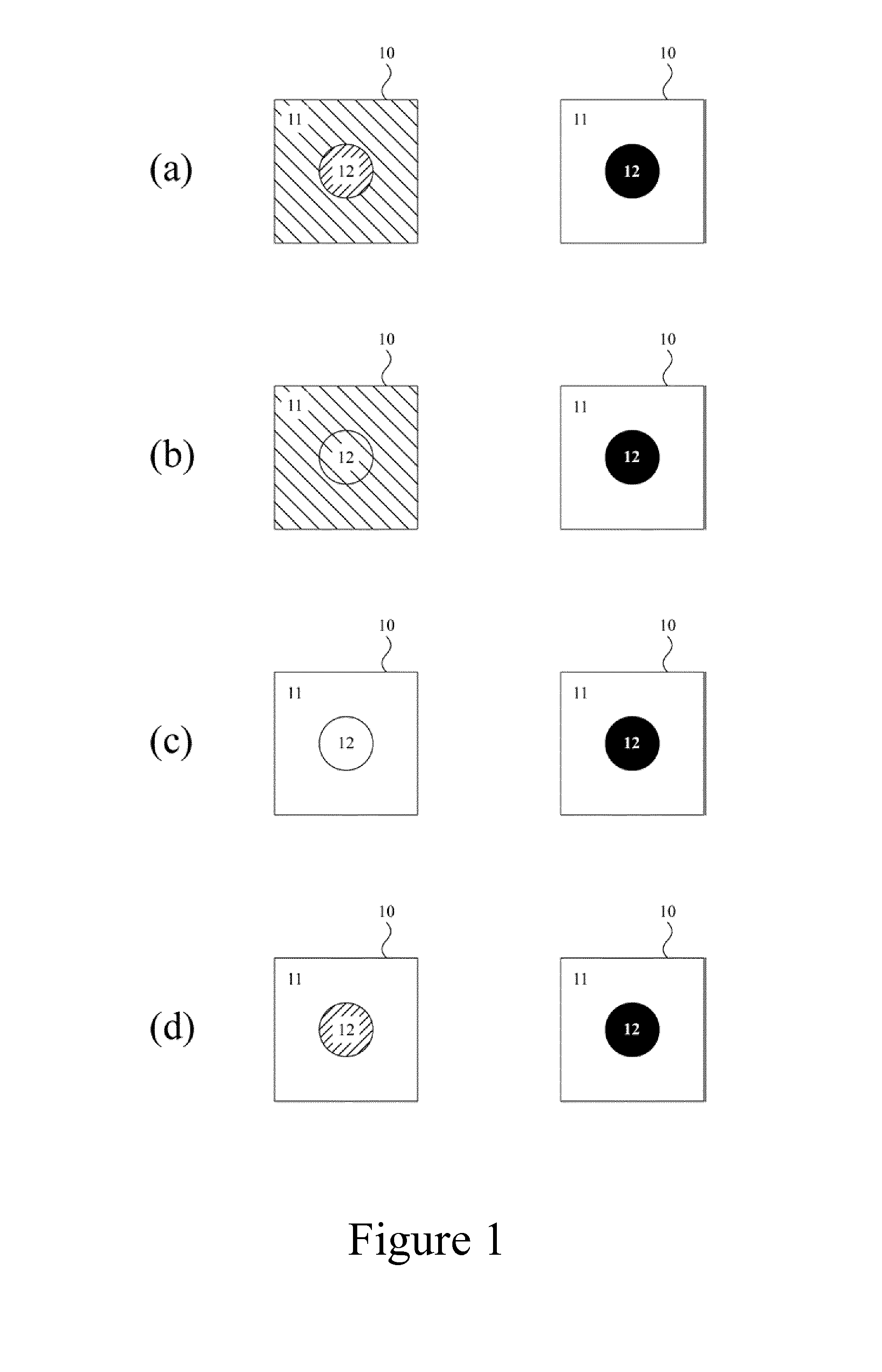
[0076]FIG. 1 schematically shows different situations of a target surface 10, having a first target surface area 11 and a second target surface area 12, under illumination with primary and secondary light outputs, respectively. In FIG. 1, the target surface 10 under illumination with the primary light output is shown on the left-hand side, and the target surface 10 under illumination with the secondary light output is shown on the right-hand side. For any illumination, the first and second target surface areas 11 and 12 have a contrast, and under illumination with the secondary light output (right-hand side) the contrast is larger than under illumination with the primary light output (left-hand side).

[0077]In FIG. 1a, the first and second target surface areas 11 and 12 have a different color under illumination with the primary light output as well as under illumination with the secondary light output. Furthermore, the color of the first target surface area 11 is different under illu...


PUM


Abstract

The invention relates to an arrangement (100) comprising a lighting system (110) and a target object (120), wherein the lighting system (110) is arranged to illuminate a target surface of the target object (120) with a primary light output (111) and with a secondary light output (112). Each of these light outputs has an illumination spectrum representing a color. The two illumination spectra are different, but the two colors are substantially the same. The target surface has a first target surface area and a second target surface area. When the first and second target surface areas are illuminated with the primary light output (111), they have a contrast that is lower than when they are illuminated with the secondary light output (112). The arrangement of the invention can be used for atmosphere creation or for attracting attention to the target object (120).

Description

FIELD OF THE INVENTION[0001]The invention relates to an arrangement comprising a lighting system and a target object, wherein the lighting system is arranged to illuminate the target object and to change the visual appearance thereof, preferably in a dynamical way. Such an arrangement can for example be used in a retail environment to draw attention to certain products. The invention also relates to a lighting device for use in the lighting system of the arrangement.BACKGROUND OF THE INVENTION[0002]In many situations it is desired to be able to change the visual appearance of an object, sometimes even in a dynamical way. For example, a retailer wants to attract a customer's attention to a product to improve the sales of the product, and such attention is typically attracted by the visual appearance of the product, by using stickers, labels, posters and other promotional material. In supermarkets, placing products on the head of gondolas or in temporary displays in the main route can...

Claims


Application Information

Patent Timeline
IPC IPC(8): F21V9/16F21S8/04F21S10/02G09F13/02
CPCF21V9/16F21S8/046F21S10/023F21Y2113/005F21Y2101/02F21W2131/405G09F13/02F21V9/30F21V9/00F21V14/02F21Y2115/10F21Y2113/13
Inventor WAGEMANS, WIEBEPLASSCHAERT, HELENA BERNADETTE JOSLENSSEN, KARS-MICHIEL HUBERTSEKULOVSKI, DRAGANKURT, RALPH
Owner SIGNIFY HOLDING B V
Why Eureka
Try Eureka