Rotary tool turret special for NC turning and milling center and rotation method

A technology of CNC center and rotary turret, applied in the direction of tool holders, etc., can solve the problems of difficult replacement of tool handles, easy loosening of tool handles, easy deflection, and up and down movement of turrets.

Inactive Publication Date: 2009-12-23
HANGZHOU BAKER MASCH CO LTD
View PDF0 Cites 4 Cited by
  • Summary
  • Abstract
  • Description
  • Claims
  • Application Information

AI Technical Summary

Problems solved by technology

[0002] In the current background technology, the locking method of the turret handle adopts the rear pull locking method. There is a pull nail at the end of the handle. The oil pressure controls the knife cylinder, and the knife cylinder acts on the butterfly spring to make the mechanical three-claw When working, the mechanical claw grabs the pull nail and then pulls it, and tightens the handle; the general turret needs to be equipped with a VDI tool holder ( Figure 2-1 ), which are not interchangeable in turning, milling, boring, drilling, and tapping. They are all special parts. Not only are the VDI tool holders expensive, the tool holder is not easy to replace, and the tool holder is prone to loosening during processing. When it is necessary to process porous parts, it is necessary to process step by step. Drilling and tapping cannot be completed at one time. For different workpieces, multi-axis devices cannot be installed, so man-hours are wasted and the processing efficiency is not good. In addition, in the spindle transmission mode, generally The main shaft transmission adopts spline transmission, and the spline manufacturing process is cumbersome and expensive
The position of the turret is easy to yaw, and the turret moves up and down (because the turret only performs radial rotation), which cannot effectively reduce friction; in addition, the rotating structure of the turret adopts a two-plate clutch structure. When the turret needs to rotate, The turret can only rotate when the indexing tooth plate is separated from the rising base, so the rotation accuracy is low and the stability is not good

Method used


Image

  • Rotary tool turret special for NC turning and milling center and rotation method
  • Rotary tool turret special for NC turning and milling center and rotation method
  • Rotary tool turret special for NC turning and milling center and rotation method

Examples


Embodiment 1

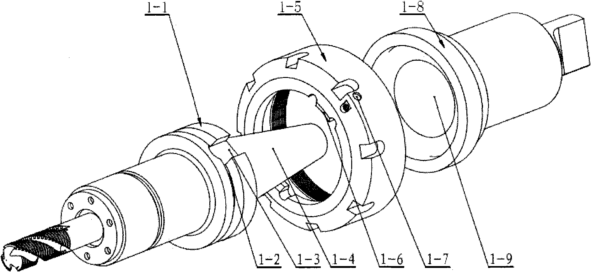
[0021] Embodiment 1: see attached Figure 1 to Figure 5 . It includes Dota ( Figure 5-1 ), the guide seat in the turret ( Figure 4-4 ) indirectly fastened to the base ( Figure 5-4 ), a round hole is opened on the normal surface of the guide seat ( Figure 4-3 ), so that the main shaft drive shaft ( Figure 4-2 ) is connected to the transmission, and the outer circular surface of the guide seat has a glyph guide groove ( Figure 4-5 ), the distance between the upper and lower ends is symmetrical to the center of the circular hole on the normal plane. One-shaped flat head handle seat ( figure 1 -8) The tail is formed into an inline flat head and is located in the inline guide groove in the guide seat. The inline flat head handle seat cooperates with the inline guide groove on the guide seat and rotates along the guide seat. wear plate ( Figure 4 -6) It is built into the inline guide groove of the guide seat and the wear-resistant sheet is located on the left side a...

Embodiment 2

[0026] Embodiment 2: On the basis of Embodiment 1, the rotation method of the special rotary turret of the turning and milling CNC center, when the turret is rotating, it drives the inline flat head tool handle seat ( figure 1 -8) With the guide seat inline guide groove ( Figure 4-5 ) for a 360-degree circular rotation, and after the turret rotates at a specific angle, the flat head at the end of the flat head handle seat is transferred into the flat groove of the main shaft drive shaft ( Pic 4-1 ) after anastomosis, the main shaft drive shaft is driven by the servo motor ( Figure 4-2 ) rotation, so that the flat-shaped flat head handle seat is rotated, and at this time, the V-shaped groove handle ( Picture 1-1 ) and tools to process the parts.

Embodiment 3

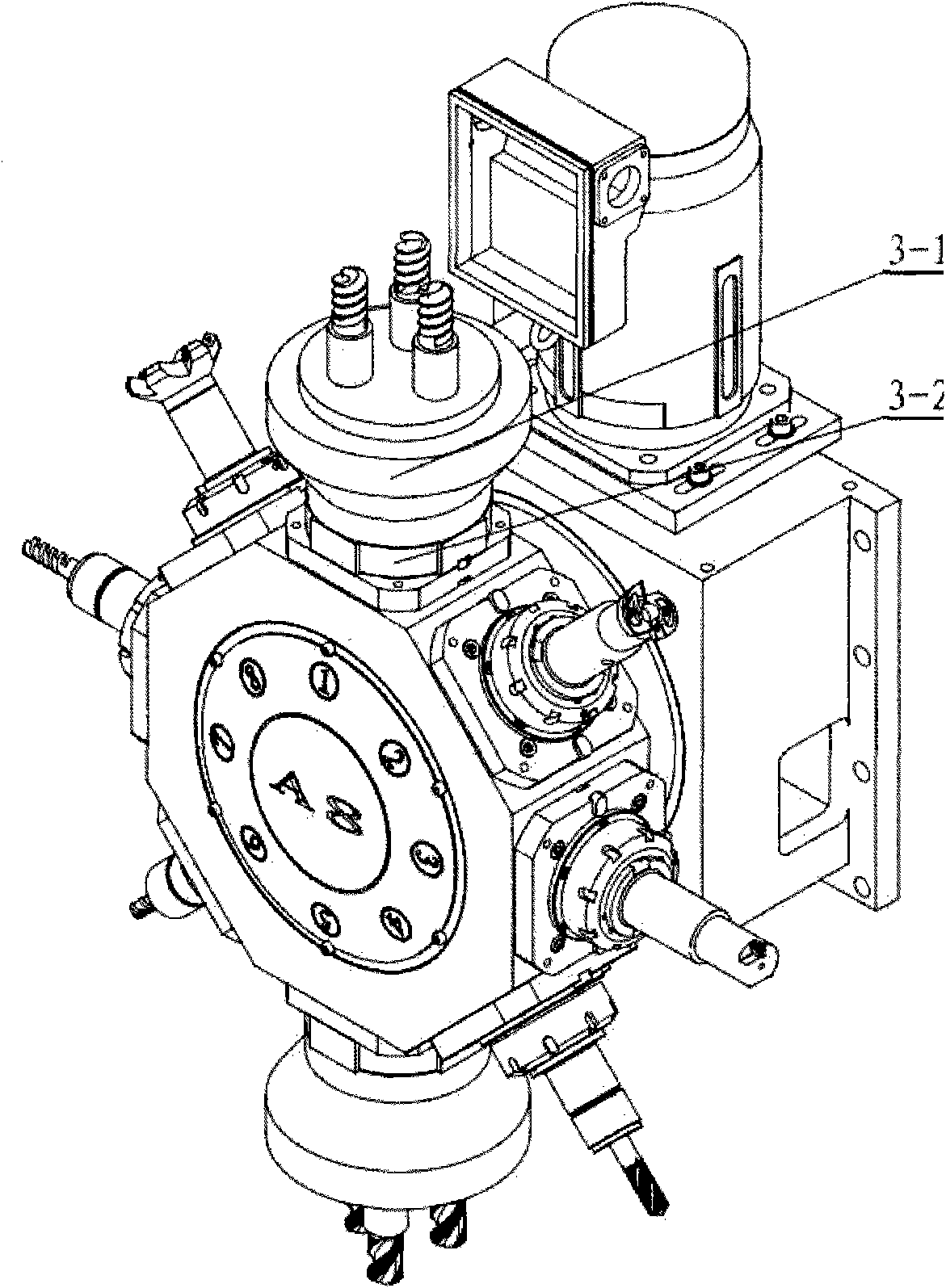
[0027] Embodiment 3: On the basis of Embodiment 1, a kind of turret rotating structure, it comprises turret, and described turret rotates and adopts three-plate clutch structure and is divided by indexing ring A ( Figure 5-3 ), indexing tooth plate B ( Figure 5-2 ), indexing tooth disc C ( Figure 5-5 ) and friction plate ( Figure 5 -6) composition, the indexing tooth plate A is fastened on the turret ( Figure 5-1 ), the index ring C is fastened to the base ( Figure 5-4 ), the indexing toothed disc B can be used for piston movement, the gears of the indexing toothed disc A and the indexing toothed disc C are aligned, and the indexing toothed disc B performs the toothing of the indexing toothed disc A and the indexing toothed disc C snap lock, servo motor and worm ( Figure 5 -9) and drive the worm wheel through the worm ( Figure 5 -7) rotation, the worm gear is installed on the cylindrical helical gear shaft ( Figure 5 -8), the outer circular helical gear of the i...


PUM


Abstract

The invention relates to a turret type rotary tool turret special for an NC turning and milling center and for turning and milling tool turrets and machining centers of NC lathes and a rotation method. A toolholder adopts the locking structure of a locknut and uses a V-shaped groove of a V-shaped groove toolholder; the V-shaped groove toolholder is locked by rotating the locknut clockwise and is loosened by rotating the locknut counterclockwise so as to be convenient for realizing the functions of installing, fixing and taking out the V-shaped groove toolholder and replacing multi-spindles; spindle transmission adopts the straight concave-convex connection transmission type; the tool turret rotation adopts the structure of a three-plate clutch which is driven to rotate by a high-precision worm gear and a high-precision worm. The invention has the following advantages: 1. short replacement time, fast speed and convenient replacement of V-shaped groove toolholders; 2. good functions of installing and replacing multi-spindles, one-time completion of drilling and tapping, shortened operation time and greatly improved machining efficiency; 3. great bearing capacity, good structure rigidity, long service life, simple machining, low manufacturing cost and convenient equipment maintenance and repair; 4. high rotary precision and good stability.

Description

technical field [0001] The invention relates to a special rotary turret and a rotation method for turning, milling, and compound turrets of CNC lathes and machining center machine turrets for turning and milling CNC centers. The turrets are divided into 4-axis, 6-axis, 8-axis, 12-axis four major specifications, belonging to the field of rotary turret manufacturing for turning and milling CNC centers. Background technique [0002] In the current background technology, the locking method of the knife handle of the turret adopts the rear-pull locking method. There is a pull nail at the end of the knife handle, and the oil pressure controls the knife cylinder. When working, the mechanical claw grabs the pull nail and then pulls it, and tightens the handle; the general turret needs to be equipped with a VDI tool holder ( diagram 2-1 ), which are not interchangeable in turning, milling, boring, drilling, and tapping. They are all special parts. Not only is the VDI tool seat expen...

Claims


Application Information

Patent Timeline
Patent Type & Authority Applications(China)
IPC IPC(8): B23B29/32
Inventor 廖竹霖
Owner HANGZHOU BAKER MASCH CO LTD
Why Eureka
Try Eureka