Mirror display, half mirror plate, and electronic device

a technology of mirror display and mirror plate, which is applied in the direction of electric digital data processing, instruments, computing, etc., can solve the problems of users' inability to use devices, and users' obstructions of difficult-to-move display devices (e.g., digital signage and television receivers), and achieve the effect of improving the design quality of devices

Active Publication Date: 2016-01-28
SHARP KK
View PDF6 Cites 39 Cited by
  • Summary
  • Abstract
  • Description
  • Claims
  • Application Information

AI Technical Summary

Benefits of technology

[0013]Since the mirror display, the half mirror plate, and the electronic device of the present invention include a reflectance adjuster, they can prevent the boundary line between the frame region and the display region from being observed in a mirror mode, improving the design quality thereof.

Problems solved by technology

Such common conventional display devices show only a black or gray screen when they show no image (for example, when they are in the power-off state), so that the devices are useless for users.
On the contrary, large-size, difficult-to-move display devices (e.g., digital signage and television receivers) can be mere obstructions for users when they are in the non-display state because they occupy the same space either in the non-display state or in the display state.

Method used


Image

  • Mirror display, half mirror plate, and electronic device
  • Mirror display, half mirror plate, and electronic device
  • Mirror display, half mirror plate, and electronic device

Examples


example 1

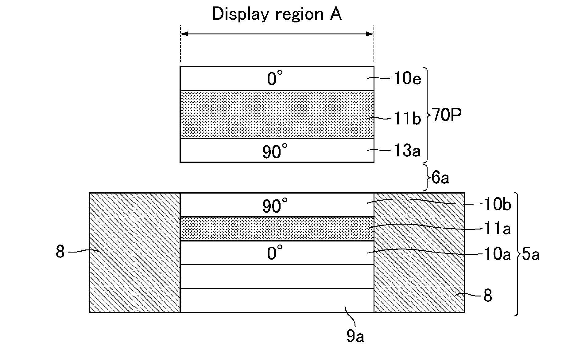
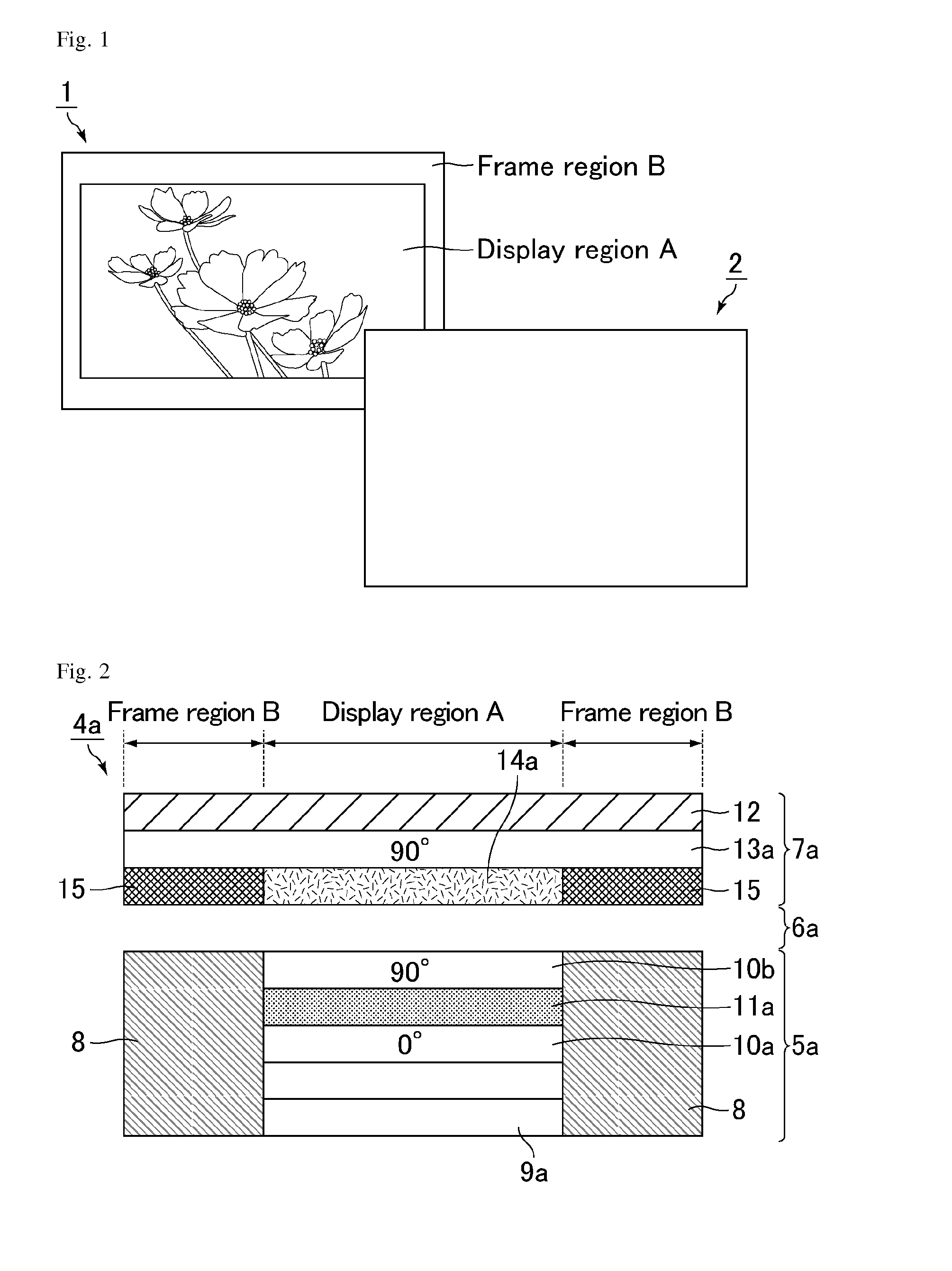
[0074]Example 1 relates to a mirror display including a liquid crystal display device, a reflective polarizing plate serving as the half mirror layer, and a black tape serving as the reflectance adjuster. The term “half mirror layer” herein means a translucent layer that has reflectivity against incident light and that preferably has a reflectance against the natural light of 40% or higher, and more preferably 50% or higher. The term “reflectance” herein means a “luminous reflectance” unless otherwise mentioned. The half mirror layer may absorb part of the incident light.

[0075]FIG. 1 is an explanatory view showing the screens of a mirror display of Example 1 in a display mode and in a mirror mode. As shown in FIG. 1, in a mirror display 1 in the display mode, a display region A shows an image and a frame region B serves as a mirror. In contrast, in a mirror display 2 in the mirror mode, the display region A and the frame region B together form a single mirror surface, so that the wh...

example 2

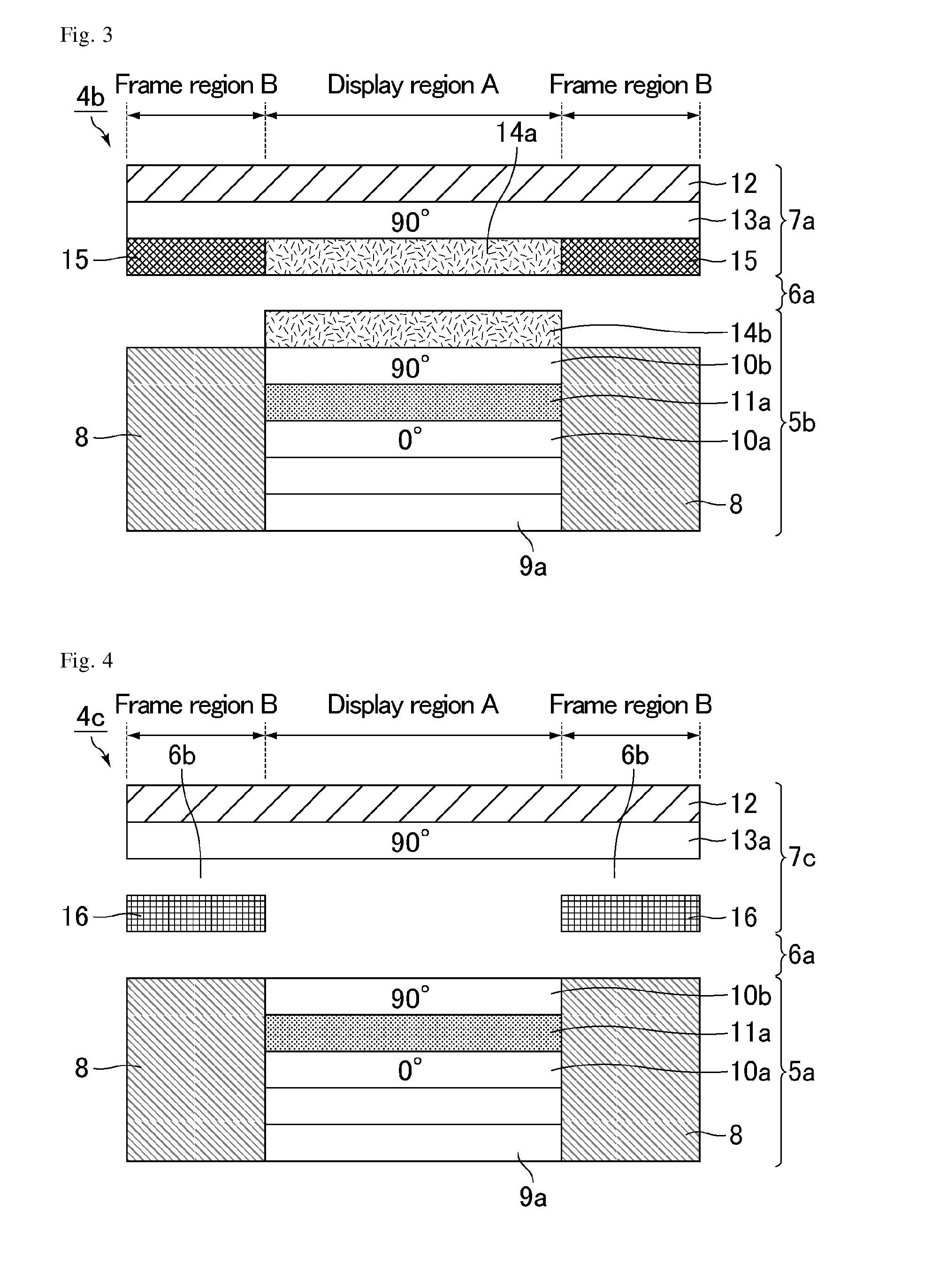
[0090]Example 2 relates to a mirror display including a liquid crystal display device, a reflective polarizing plate serving as the half mirror layer, and a black tape serving as the reflectance adjuster. The difference from Example 1 is that an anti-reflection film is provided for the liquid crystal display device. FIG. 3 is a schematic cross-sectional view showing the structure of a mirror display of Example 2. As shown in FIG. 3, an anti-reflection film 14b was stacked on the position closer to a viewer than the viewer-side absorptive polarizing plate 10b of a liquid crystal display device 5b with acrylic pressure-sensitive adhesive (not shown).

[0091]The driving principles in the display mode and in the mirror mode are substantially the same as those in Example 1, so that the explanation of the same respects is omitted here. With respect to a mirror display 4b of Example 2, the light passing through the reflective polarizing plate 13a in the display region A is hardly reflected o...

example 3

[0092]Example 3 relates to a mirror display including a liquid crystal display device, a reflective polarizing plate serving as the half mirror layer, and black paper serving as the reflectance adjuster. The difference from Example 1 is that the black tape, which is attached to the reflective polarizing plate and serves as the reflectance adjuster, is replaced by the black paper disposed apart from the reflective polarizing plate and that no anti-reflection film is disposed on the back side of the half mirror plate. FIG. 4 is a schematic cross-sectional view showing the structure of a mirror display of Example 3. As shown in FIG. 4, black paper 16 is disposed in a region (frame region B) that does not overlap the display region of the liquid crystal display device 5a with an air layer 6b interposed therebetween. The black paper 16 constitutes part of a half mirror plate 7c.

[0093]The driving principles in the display mode and in the mirror mode are substantially the same as those in...


PUM

PropertyMeasurementUnit
reflectanceaaaaaaaaaa

Abstract

The present invention provides a mirror display which prevents the boundary line between a frame region and a display region from being observed in a mirror mode and which thus has improved design quality. The mirror display of the present invention includes a half mirror plate including a half mirror layer, and a display device disposed behind the half mirror plate, the display device including a display panel and a frame component that supports a peripheral portion of the display panel, and the mirror display including a reflectance adjuster that makes equal the reflectance in a display region where the half mirror layer and the display panel face each other and the reflectance in a frame region where the half mirror layer and the frame component face each other.

Description

TECHNICAL FIELD[0001]The present invention relates to a mirror display, a half mirror plate, and an electronic device. The present invention specifically relates to a mirror display that can be driven in both a mirror mode in which the display serves as a mirror and a display mode in which the display shows an image, a half mirror plate to be used in the mirror display, and an electronic device including the mirror display.BACKGROUND ART[0002]FIG. 39 is an explanatory view showing the display states in the power-on state and in the power-off state of a common conventional display device. As shown in FIG. 39, a display device 101 in the power-on state shows an image in a display region A. A region (frame region B) called a frame or a bezel in the periphery of the display region A does not contribute to image display. In contrast, a display device 102 in the power-off state shows no image in the display region A, and the frame region B still does not contribute to image display.[0003]...

Claims


Application Information

Patent Timeline
Patent Type & Authority Applications(United States)
IPC IPC(8): G02F1/1335G02F1/1333G06F3/14
CPCG02F1/133555G06F3/1446G02F2001/133388G02F1/133308G02F2001/133557G02F1/133536G02F1/13471G02F2201/08G02F2203/09G02F1/133331G02F1/133388G02F1/133557G02F1/133601G02F1/133531G02F1/133541
Inventor SAKAI, AKIRANISHIYAMA, TAKAYUKIHASEGAWA, MASAHIROYOSHIDA, HIDEFUMIMIZUSHIMA, SHIGEAKI
Owner SHARP KK
Why Eureka
Try Eureka