Restoration filter generation device and method, image processing device, imaging device, and non-transitory computer-readable medium

a technology of restoration filter and restoration filter, which is applied in the field of restoration filter generation device and method, image processing device, restoration filter generation program, and non-transitory computer-readable medium, can solve the problems of disadvantageous increase in arithmetic load, and achieve the effect of reducing the arithmetic load

Active Publication Date: 2016-01-28
FUJIFILM CORP
View PDF3 Cites 22 Cited by
  • Summary
  • Abstract
  • Description
  • Claims
  • Application Information

AI Technical Summary

Benefits of technology

[0038]According to the present invention, the restoration filter is generated for the restoration process performed only on the luminance system image data having a large visual effect that is the image data whose magnification chromatic aberration is corrected, reducing the arithmetic load in the restoration process. Particularly, the correction residual amount of the magnification chromatic aberration correction is taken into account to generate the restoration filter with respect to the luminance system image data, which enables the proper restoration process to be performed on the luminance system image data.

Problems solved by technology

For this reason, the restoration process by use of the restoration filter needs to be performed for each color component, which disadvantageously increases the arithmetic load.

Method used


Image

  • Restoration filter generation device and method, image processing device, imaging device, and non-transitory computer-readable medium
  • Restoration filter generation device and method, image processing device, imaging device, and non-transitory computer-readable medium
  • Restoration filter generation device and method, image processing device, imaging device, and non-transitory computer-readable medium

Examples


first embodiment

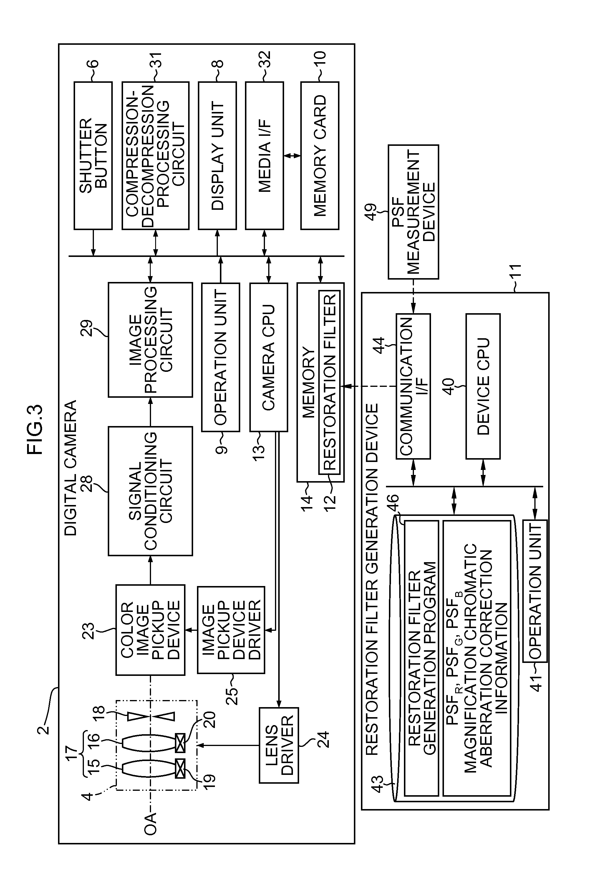
[0104]FIG. 7 is a block diagram showing a first embodiment of the restoration filter generation device 11 and is a functional block diagram mainly showing a functionality of the device CPU 40 shown in FIG. 3.

[0105]The device CPU 40 includes the first and second transfer function acquisition parts 51 and 52 (first and second transfer function acquisition device), the third transfer function calculation part 53 (third transfer function calculation device), the correction information acquisition part 56 (correction information acquisition device), and the restoration filter generation part 57 (restoration filter generation device).

[0106]The first transfer function acquisition part 51 acquires from the storage 43 the first transfer functions (PSFR, PSFG, and PSFB for the respective colors of RGB) concerning the point spread of the optical system 17 to output the PSFR, PSFG, and PSFB, and the gravity center positions αR(r), αG(r), and αB(r) of the PSFR, PSFG, and PSFB to the second trans...

second embodiment

[0118]FIG. 8 is a block diagram showing a second embodiment of the restoration filter generation device 11, and is a functional block diagram mainly showing a functionality of the device CPU 40 shown in FIG. 3. Parts in common with the first embodiment shown in FIG. 7 are designated by the same reference numerals and a detailed description thereof is omitted.

[0119]In FIG. 8, a correction information acquisition part 56a (correction accuracy evaluation device) acquires from the storage 43 the correction amounts βR(r) and βB(r) for correcting the magnification chromatic aberration of the optical system 17 as well as information indicating reliability of the magnification chromatic aberration correction on the basis of the correction amounts βR(r) and βB(r) (information indicating reliability of the correction amounts βR(r) and βB(r) or correction residual amounts γR(r) and γB(r) of the magnification chromatic aberration).

[0120]In other words, in a situation where the correction amount...

third embodiment

[0124]FIG. 9 is a block diagram showing a third embodiment of the restoration filter generation device 11 and is a functional block diagram mainly showing a functionality of the device CPU 40 shown in FIG. 3. Parts in common with the first and second embodiments shown in FIG. 7 and FIG. 8 are designated by the same reference numerals and a detailed description thereof is omitted.

[0125]The third embodiment is an embodiment in which the method for generating the restoration filter is switched over depending on whether or not the reliability of the magnification chromatic aberration correction is low as in the second embodiment.

[0126]In FIG. 9, a fourth transfer function calculation part 54 (fourth transfer function calculation device) receives the PSFR, PSFG, and PSFB for the respective colors of RGB from the first transfer function acquisition part 51 to calculate MTFR(ωx,ωy), MTFG(ωx,ωy), and MTFB(ωx,ωy) obtained by removing the phase information from the PSFR, PSFG, and PSFB, respe...


PUM


Abstract

A restoration filter generation device that generates a restoration filter for a restoration process on the basis of a point spread in an optical system, the restoration process being performed on luminance system image data as image data concerning a luminance which is generated on the basis of image data for each color of plural colors acquired by an image pickup device having the optical system, the restoration filter generation device includes a first transfer function acquisition device, a correction information acquisition device, a second transfer function acquisition device, a third transfer function calculation device, and a restoration filter generation device that generates the restoration filter for the restoration process on the basis of the third transfer function calculated by the third transfer function calculation device.

Description

CROSS-REFERENCE TO RELATED APPLICATIONS[0001]This application is a Continuation of PCT International Application No. PCT / JP2013 / 080649 filed on Nov. 13, 2013, which claims priority under 35 U.S.C §119(a) to Japanese Patent Application No. 2013-042187 filed on Mar. 4, 2013. Each of the above application(s) is hereby expressly incorporated by reference, in its entirety, into the present application.BACKGROUND OF THE INVENTION[0002]1. Field of the Invention[0003]The present invention relates to a restoration filter generation device and method, an image processing device, an imaging device, a restoration filter generation program, and a non-transitory computer-readable medium, and particularly relates to a technology of generating a restoration filter for performing a restoration process on an image captured via an optical system on the basis of a point spread function (PSF) or optical transfer function (OTF) of the optical system.[0004]2. Description of the Related Art[0005]The restor...

Claims


Application Information

Patent Timeline
Patent Type & Authority Applications(United States)
IPC IPC(8): G06T5/00G06T5/20H04N1/58H04N1/60H04N9/04
CPCG06T5/003H04N9/045H04N1/6027G06T2207/10024G06T5/20G06T2207/20024G06T2207/20056H04N1/58H04N1/409G06T2207/20008H04N23/81H04N23/632H04N25/6153H04N23/843
Inventor NARUSE, YOUSUKEHAYASHI, KENKICHISUGIMOTO, MASAHIKO
Owner FUJIFILM CORP
Why Eureka
Try Eureka