

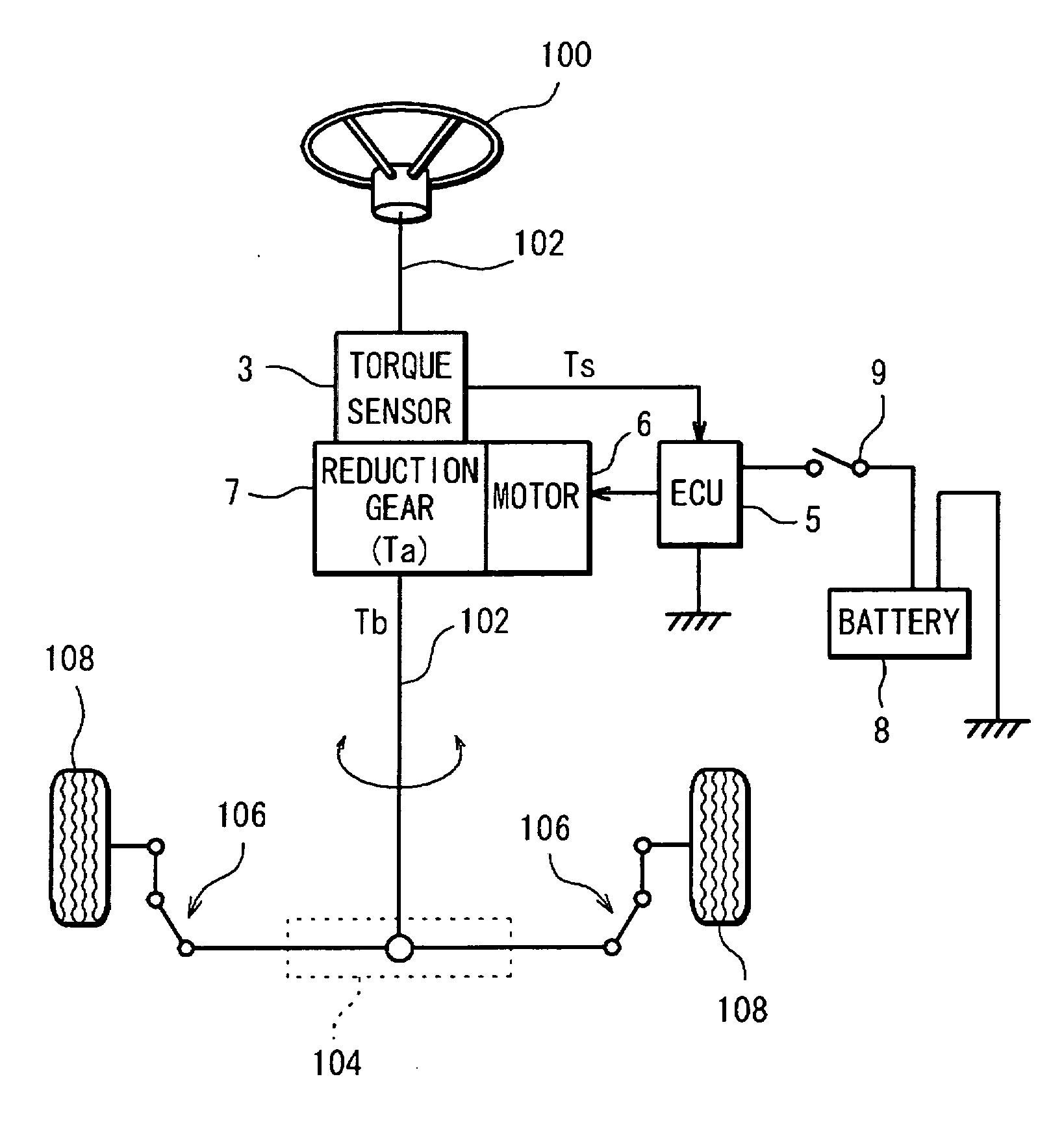
Electric power steering system
a technology of electric power steering and steering wheel, which is applied in the direction of steering initiation, instruments, vessel construction, etc., can solve the problems of increased response lag, decreased gain of phase compensating means in a normal steering speed region, adverse steering feeling, etc., and achieves reduced arithmetic load, large design freedom, and easy attainment of desired characteristics
- Summary
- Abstract
- Description
- Claims
- Application Information
AI Technical Summary
Benefits of technology
Problems solved by technology
Method used
Image

Examples
example
[0056] Transfer Function P(s) of Control Target (Second-Order Lag System):
P(s)=(ω12 / (s2+2ζ2ω1+ω12))·(ω2 / (s+ω2))
[0057] Provided that ω1=16.5×2π, ω2=300×2π and ζ=0.4, a Bode diagram of the control target exhibits curves (e) shown in FIG. 5. In the control target, a resonance peak appears at 16.5 Hz, whereas the phase lag occurs at high frequencies.
[0058] The control target is subjected to the resonance eliminating filter portion 15 (transfer function G1(s)·G2(s)), [0059] where ω1=10×2π, ζ11=0.5, ζ12=1.1, and [0060]ω2=6×2π, ζ21=1.3, ζ22=1.05.
In this case, a Bode diagram of the resonance eliminating filter portion 15 exhibits curves (f) shown in FIG. 5. On the other hand, the control target subjected to the resonance eliminating filter portion 15 exhibits characteristics represented by curves (g) in FIG. 5.
[0061]FIG. 6 shows a Bode diagram of a comparative example wherein the control target (transfer function P(s)) is subjected to the band-stop filter 15a alone. In FIG. 6, curves ...
PUM
 Abstract
Description
Claims
Application Information