Surveying Instrument

a technology of a surveillance instrument and a control module, applied in the field of surveillance instruments, can solve the problems of increasing cost, increasing cost, increasing cost, etc., and achieve the effects of reducing the arithmetic load of the control module, reducing manufacturing cost, and high performance of the control modul

Active Publication Date: 2019-05-30
KK TOPCON
View PDF0 Cites 4 Cited by
  • Summary
  • Abstract
  • Description
  • Claims
  • Application Information

AI Technical Summary

Benefits of technology

[0014]According to the present invention, comprises: a surveying instrument which is installed in a room and performs a measurement at a plurality of installation points, wherein the surveying instrument comprises a first measuring component and a second measuring component which are provided on a frame, wherein the first measuring component comprises a horizontal rotation driving unit for horizontally rotating the frame around a vertical axis, a horizontal angle detector for detecting a horizontal angle of the frame, a telescope incorporating a first distance measuring unit for sighting a predetermined measuring point, emitting the first distance measuring light, and measuring a distance, a first vertical rotation driving unit for vertically rotating the telescope around a horizontal axis, a first vertical angle detector for detecting a vertical angle of the telescope, and a control module, wherein the second measuring component comprises a second distance measuring unit for emitting the second distance measuring light which is a pulsed light and measuring a distance in accordance with each pulsed light, a scanning mirror for deflecting the second distance measuring light within a vertical plane, a second vertical rotation driving unit for vertically rotating the scanning mirror around a horizontal axis, and a second vertical angle detector for detecting a vertical angle of the scanning mirror, wherein the control module acquires point cloud data of a whole circumference in the room with the use of the second measuring component in accordance with each installation point, makes the first measuring component to measure a predetermined position in the room, prepares outer shape data of a same height and a same shape in accordance with each installation point based on a measurement result of the first measuring component or the second measuring component, performs a shape matching of each outer shape data, and registers each point cloud data based on a movement amount and a rotation amount at the time of performing the shape matching. As a result, each of the point cloud data can be registered by the two-dimensional movement and the two-dimensional rotation alone, an arithmetic load to the control module can be reduced, the high performance of the control module does not have to be realized, and a reduction in manufacturing cost can be achieved.

Problems solved by technology

When the three-dimensional point cloud data are acquired by the three-dimensional laser scanner, in particular indoor, there is a case where the three-dimensional point cloud data of an entire room cannot be acquired by the measurement performed at one point due to a shape of the room and an obstacle.
For this reason, a total station or the like for the measurement of the coupling points is additionally required, which leads to an increase in cost.
Therefore, an arithmetic device used in the surveying instrument must be a high-performance type, which leads to an increase in cost.

Method used


Image

  • Surveying Instrument
  • Surveying Instrument
  • Surveying Instrument

Examples


first embodiment

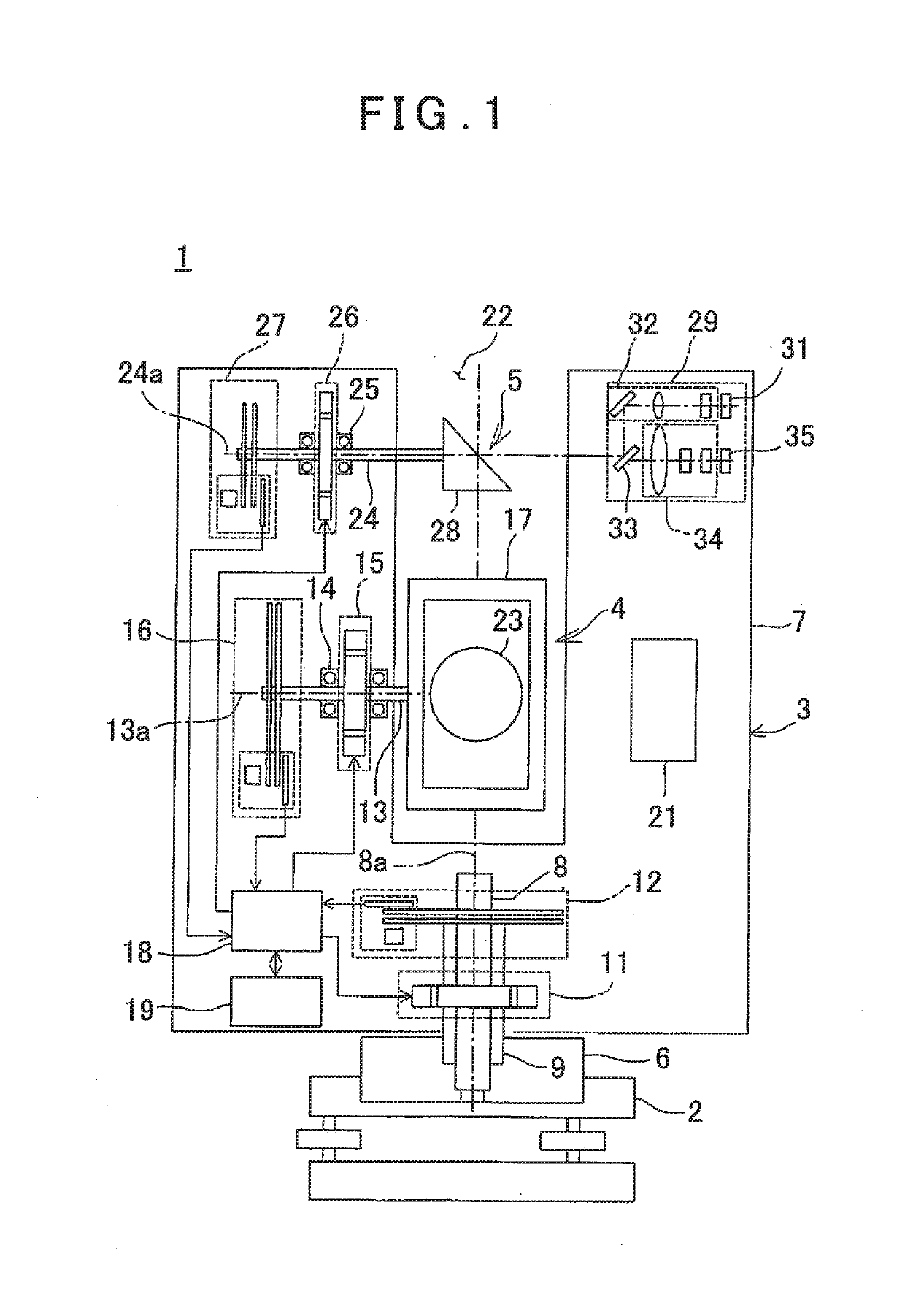
[0028]First by referring to FIG. 1, a description will be given on a surveying instrument according to the present invention.

[0029]A surveying instrument 1 has a leveling unit 2 mounted on a tripod (not shown) and a surveying instrument main body 3 mounted on the leveling unit 2. The surveying instrument main body 3 has a configuration in which a total station as a first measuring component 4 and a two-dimensional laser scanner as a second measuring component 5 are integrated. It is to be noted that the leveling may be manually performed by the leveling unit 2 or may be automatically performed by a control module 18 (to be described later). The control module 18 is, for instance, a CPU, or a PC or the like may be used as the control module 18.

[0030]The first measuring component 4 comprises a fixed portion 6, a frame 7, a horizontal rotation shaft 8, a horizontal rotation bearing 9, a horizontal rotation motor 11 as a horizontal rotation driving unit, a horizontal angle encoder 12 as...

second embodiment

[0098]Next referring to FIG. 1 and FIG. 8, a description will be given on the present invention. It is to be noted that, in FIG. 8, the same components as shown in FIG. 4 are referred by the same symbols, and a detailed description thereof will be omitted.

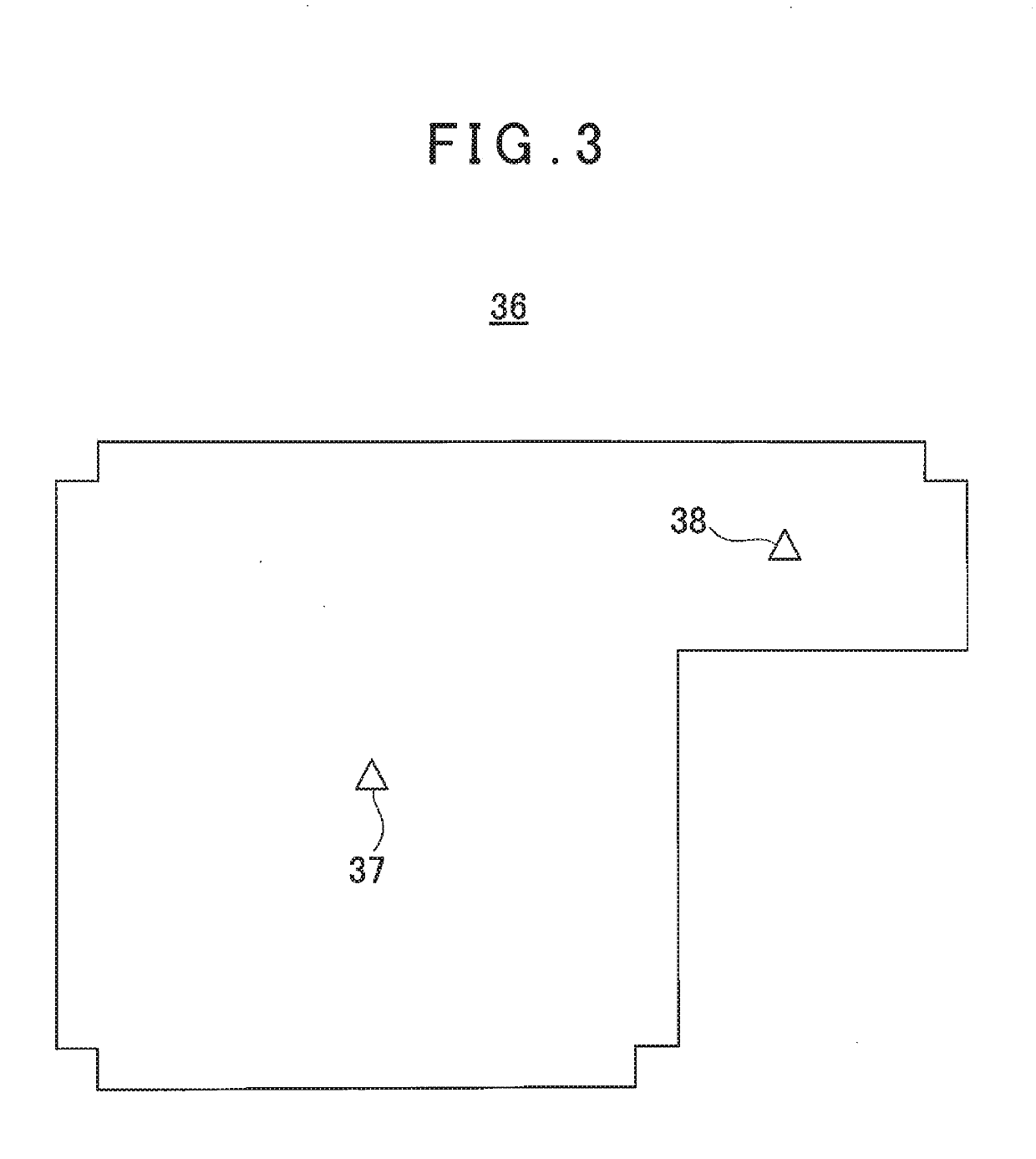
[0099]In the second embodiment, both a first installation point 37 (see FIG. 3) and a second installation point 38 (see FIG. 3) are placed on a horizontal plane, an installation surfaces of the first installation point 37 and the second installation point 38 have the different heights, and the heights are unknown. At, the time of installing a surveying instrument 1 at the first installation point 37 and at the time of installing the surveying instrument 1 at the second installation point 38, the leveling is performed, respectively.

[0100]Further, in the second embodiment, an operation unit 21 is used to specify the same arbitrary reference measuring point 49 which can be measured from the first installation point 37 and the second i...

third embodiment

[0110]Next, referring to FIG. 1, FIG. 9, and a flowchart of FIG. 10, a description will be given on the present invention. It is to be noted that, in FIG. 9, the same components as shown in FIG. 4 are referred by the same symbols, and a detailed description will thereof be omitted.

[0111]In the third embodiment, an installation surface of a first installation point 37 (see FIG. 3) and an installation surface of a second installation point 38 (see FIG. 3) are horizontal or inclined, or the two installation surfaces have the different heights. Further, a horizontal angle of a second distance measuring optical axis of a second measuring component 5 is offset from a horizontal angle of a first distance measuring optical axis of a first measuring component 4 in a rotating direction of a frame 7 at a predetermined angle, for instance, 0.6°. Therefore, the second measuring component 5 performs the rotatory irradiation (scanning) within a vertical plane which horizontally rotates at 0.6° wit...


PUM


Abstract

A surveying instrument comprises a first measuring component having a control module and a second measuring component, wherein the control module acquires point cloud data of a whole circumference in a room with the use of the second measuring component in accordance with each installation point, makes the first measuring component to measure a predetermined position in the room, prepares outer shape data of a same height and a same shape in accordance with each installation point based on a measurement result of the first measuring component or the second measuring component, performs a shape matching of each outer shape data, and registers each point cloud data based on a movement amount and a rotation amount at the time of performing the shape matching.

Description

BACKGROUND OF THE INVENTION[0001]The present invention relates to a surveying instrument which can acquire a point cloud data of an object to be measured.[0002]As a surveying instrument, there is a total station or a three-dimensional laser scanner. The total station is used for measuring a point to be measured. The three-dimensional laser scanner acquires a shape of an object to be measured as a group of innumerable points each having a three-dimensional coordinate, that is, a three-dimensional point cloud data.[0003]When the three-dimensional point cloud data are acquired by the three-dimensional laser scanner, in particular indoor, there is a case where the three-dimensional point cloud data of an entire room cannot be acquired by the measurement performed at one point due to a shape of the room and an obstacle. In this case, when the three-dimensional point cloud data are acquired at a plurality of points and a plurality of the three-dimensional point cloud data as acquired are ...

Claims


Application Information

Patent Timeline
Patent Type & Authority Applications(United States)
IPC IPC(8): G01S17/42G01S7/481G01S17/89
CPCG01S17/42G01S7/4817G01C15/002G01S17/89G01S7/481G06T2207/10028G06T7/30G01C3/08
Inventor KUMAGAI, KAORUYOSHINO, KEN-ICHIRO
Owner KK TOPCON
Why Eureka
Try Eureka