LED module

Active Publication Date: 2016-01-28
CITIZEN ELECTRONICS CO LTD +1
View PDF4 Cites 0 Cited by
  • Summary
  • Abstract
  • Description
  • Claims
  • Application Information

AI Technical Summary

Benefits of technology

[0015]According to the LED module described above, the two frame members form the inner and outer mounting areas, and the electrodes for applying the voltage to the LEDs disposed in the inner mounting a

Problems solved by technology

Furthermore, the electrodes, each disposed between the dev

Method used


Image

  • LED module
  • LED module
  • LED module

Examples


Example

[0025]An LED module according to the present invention will be described below with reference to the drawings. It is noted that the technical scope of the present invention is not limited to the embodiments thereof, but extends to the invention described in the claims and equivalents thereof.

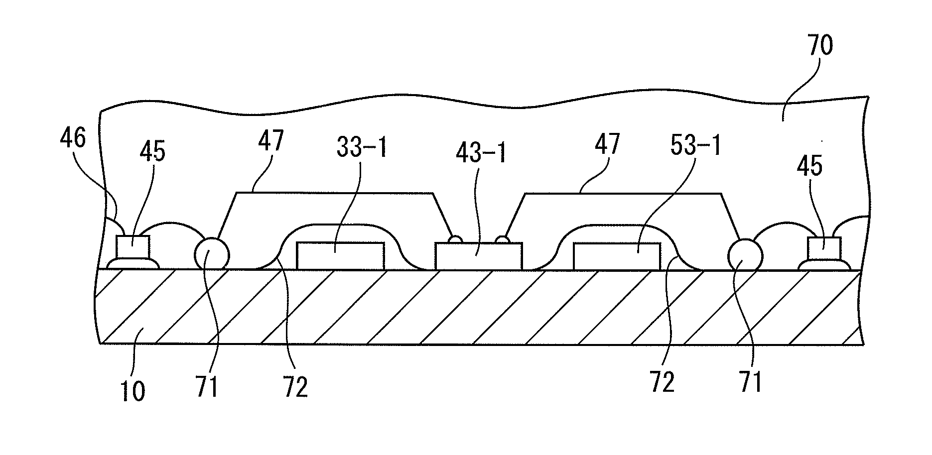
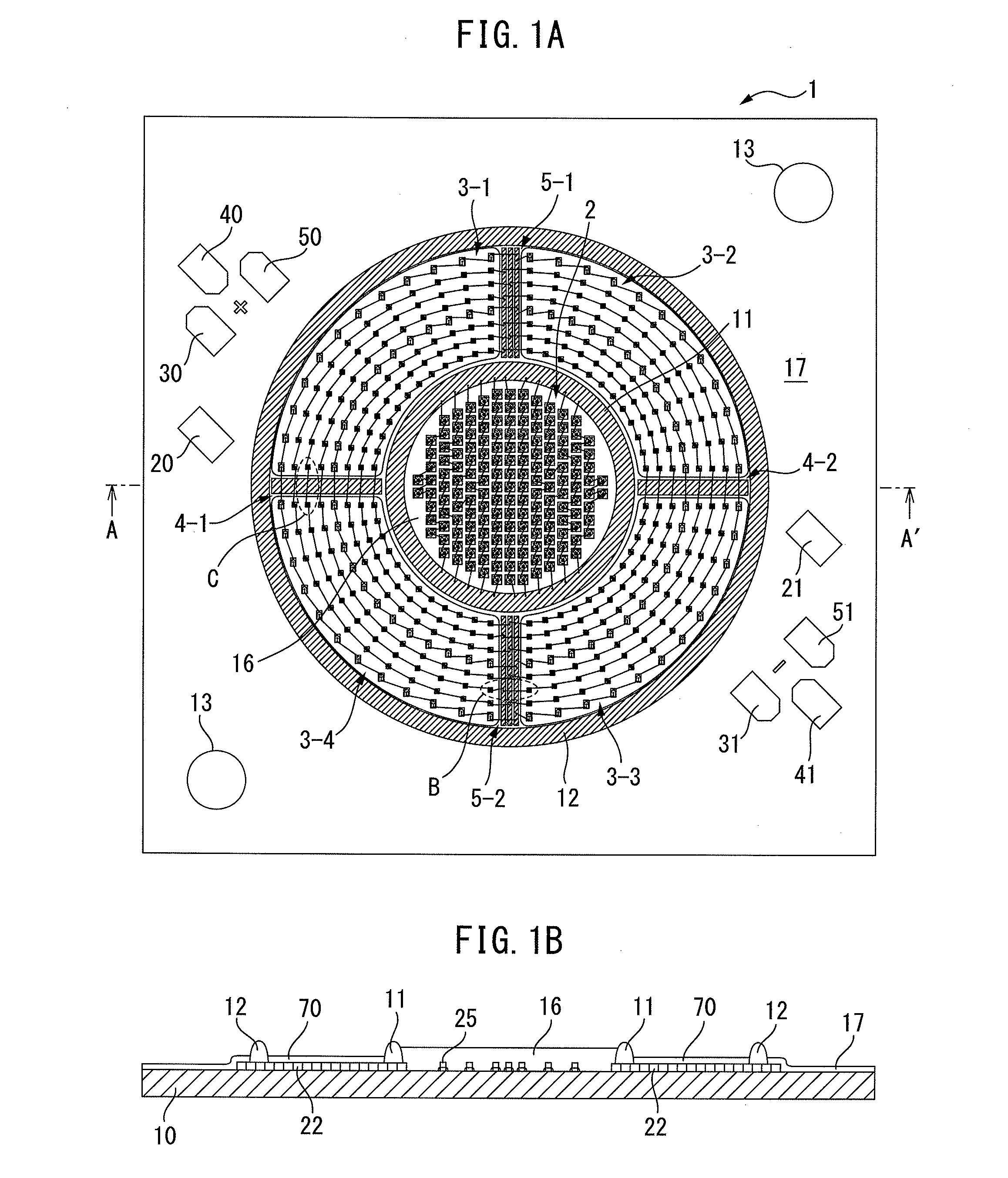
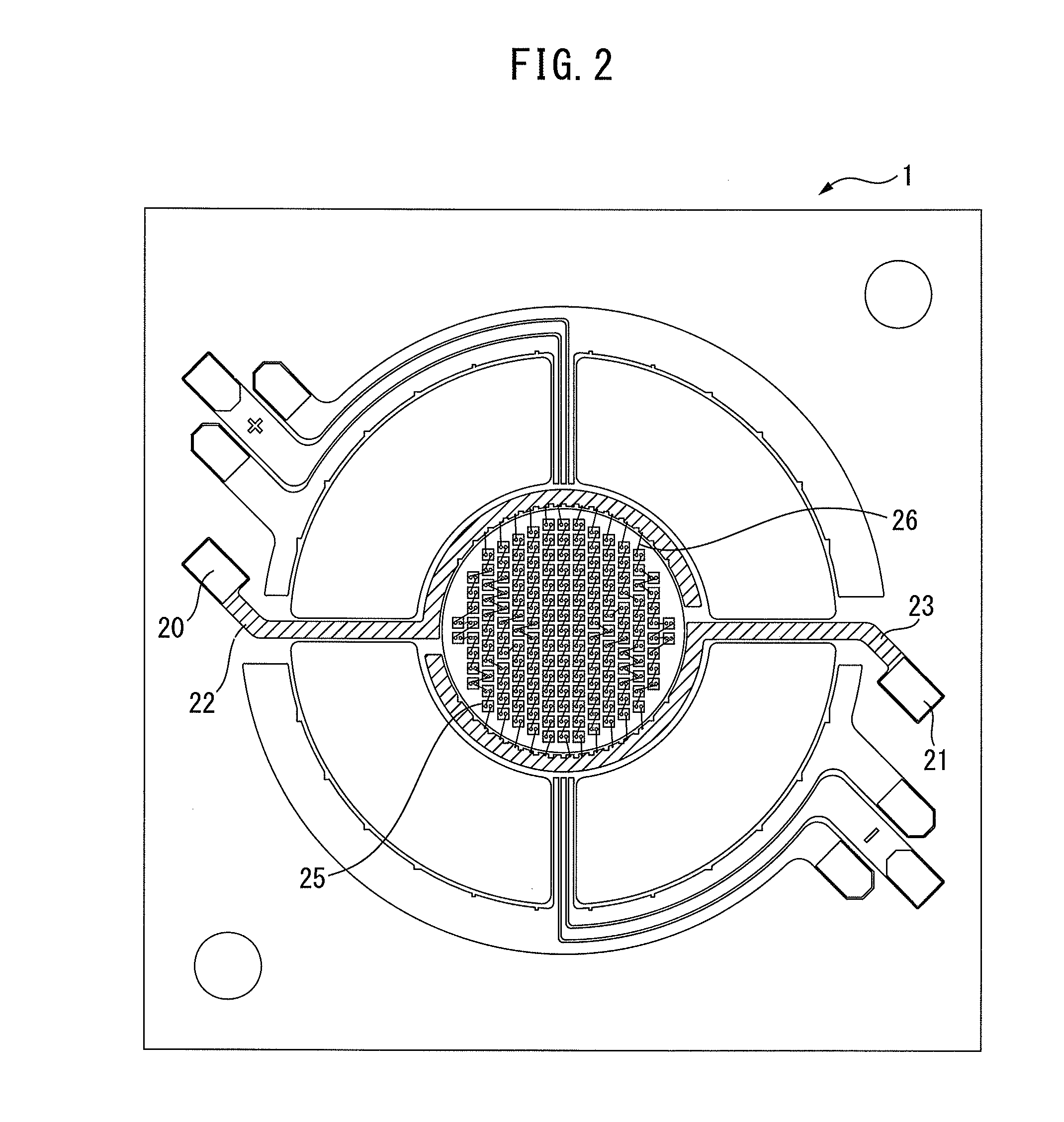
[0026]FIG. 1A is the top plan view of an LED module 1 according to the present invention, and FIG. 1B is the cross-sectional view taken along the line AA′ in FIG. 1A.

[0027]The LED module 1 is constituted of an aluminum substrate 10, various electrodes, a first frame member 11, a second frame member 12, LEDs of various colors, a phosphor resin16, and the like. The LED module 1 is attached to a lighting fixture or the like using guide holes 13 provided at its end portions.

[0028]As shown in FIG. 1A, the first frame member 11 and the second frame member 12 are concentrically disposed. A first mounting area 2 is provided within the first frame member 11. Second to fifth mounting areas 3-1 to 3-4 are ...


PUM


Abstract

An object is to provide an LED module that eliminates the need for providing electrodes between each device and allows LEDs to be arrayed with high density. An LED module includes a substrate, a first frame member, a second frame member disposed outside the first frame member, a plurality of LEDs for producing white light disposed within the first frame member, a phosphor resin disposed within the first frame member, a plurality of LEDs for producing colored light disposed between the first frame member and the second frame member, and electrodes for applying a voltage to the plurality of LEDs for producing the white light, wherein a metal wire to connect the plurality of LEDs for producing the colored light to one another is disposed so as to straddle a part of each of the electrodes.

Description

CROSS-REFERENCE TO RELATED APPLICATIONS[0001]This application is a new U.S. patent application that claims benefit of JP 2014-152381, filed on Jul. 25, 2014, the entire content of JP 2014-152381 is hereby incorporated by reference.TECHNICAL FILED[0002]The present invention relates to an LED module, and more specifically relates to an LED module that can emit white light and light of full colors by itself.BACKGROUND OF THE INVENTION[0003]LEDs, i.e., semiconductor devices that are compact in size and emit light of bright colors with high luminous efficiency, as well as having a long life and high drive performance, are becoming widely used in recent years for lighting and the like.[0004]An LED module is known in which blue LEDs and a phosphor resin layer to emit yellow light of 3500K are disposed inside, and blue LEDs and a phosphor resin layer to emit white light of 6500K are disposed outside. The LED module mixes the yellow light and the white light (see Japanese Patent Application ...

Claims


Application Information

Patent Timeline
IPC IPC(8): H01L33/62H01L27/15
CPCH01L27/156H01L33/62F21K9/00H01L25/0753H01L2224/48137H01L2924/0002
Inventor KURIKI, SHINGOSHIMOZAWA, ARATABABA, NOBUYUKIMIKAMI, TAKAHIRO
Owner CITIZEN ELECTRONICS CO LTD
Why Eureka
Try Eureka