Line system for a vehicle

a technology for a line system and a vehicle, which is applied in the direction of hose connection, connection contact member material, coupling device connection, etc., can solve the problem of risk of a buildup of electrostatic charge of the fuel line, and achieve the effect of simple durable connection and convenient placement of the fuel lin

Inactive Publication Date: 2016-01-28
AUDI AG
View PDF6 Cites 5 Cited by
  • Summary
  • Abstract
  • Description
  • Claims
  • Application Information

AI Technical Summary

Benefits of technology

[0007]In accordance with the present invention, the electrically conductive connection between the contact element and the inner layer can be realized in a single operating step at a same time as the fuel line is coupled with the connection element. As a result, installation time can be shortened. There is no need for additional elements in order to produce the electrically conductive connection between the fuel line and the connection element, because the fuel line presses the contact element against the connection element. The connection element may, for example, connect the fuel line with further fuel lines and / or a fuel tank and / or a fuel rail configured as a fuel pump. The electric charge can be reliably dissipated in almost any region of the line system. Advantageously, the contact element may also be coupled with a ground potential and / or with a cable harness in order to realize a grounding of the corresponding fuel line for example. Coupling with the ground potential may be realized, for example, by coupling the contact element with a vehicle body. As a result of the afore-described electric connection, grounding of fuel-carrying lines can advantageously be achieved in a manner that is durable and can quickly be realized.
[0017]According to another advantageous feature of the present invention, the connection element may have at least one undulated and / or rib-shaped elevation in the connection zone. The presence of such an undulated and / or rib-shaped elevation causes a widening of the fuel line to thereby realize a simple durable connection between the fuel line and the connection element. Moreover, the undulated and / or rib-shaped elevation may be oriented such that the placement of the fuel line upon the contact element requires less force than a removal of the fuel line.

Problems solved by technology

When fuel flows through the fuel line, there is a risk of a buildup of an electrostatic charge of the fuel line.

Method used


Image

  • Line system for a vehicle
  • Line system for a vehicle

Examples


Embodiment Construction

[0020]The depicted embodiment is to be understood as illustrative of the invention and not as limiting in any way. It should also be understood that the figure is not necessarily to scale and that the embodiment is sometimes illustrated by graphic symbols, phantom lines, diagrammatic representations and fragmentary views. In certain instances, details which are not necessary for an understanding of the present invention or which render other details difficult to perceive may have been omitted.

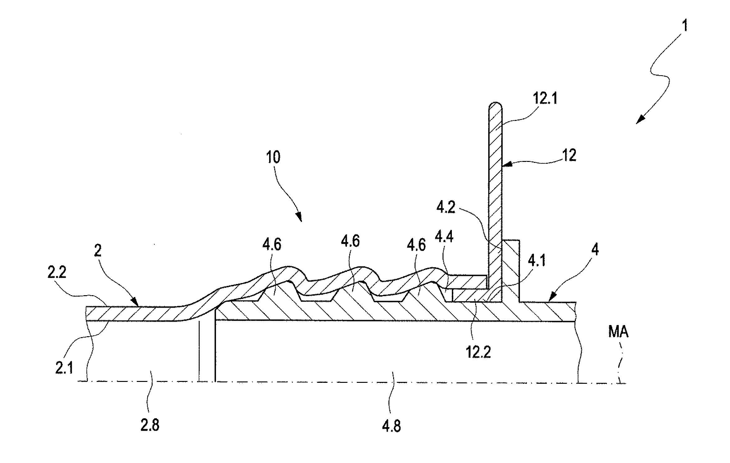
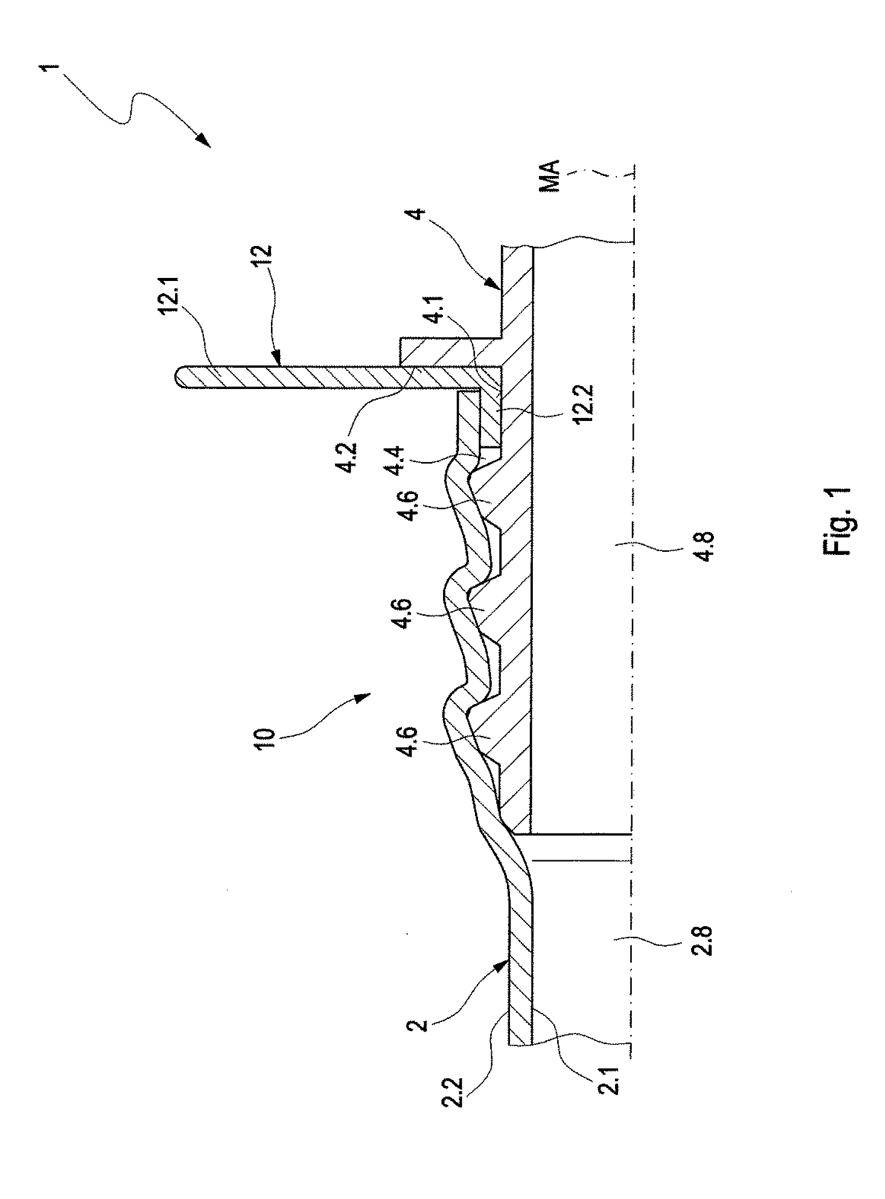
[0021]Turning now to FIG. 1, there is shown a schematic sectional view of a line system for a vehicle in accordance with the present invention, generally designated by reference numeral 1. The line system 1 includes at least one fuel line 2 having an electrically conductive inner layer 2.1 and coupled with a connection element 4 in a connection zone 10. Arranged in the connection zone 10 is an electrically conductive contact element 12 which is electrically-conductively connected with the inner...


PUM


Abstract

A line system for a vehicle includes a fuel line having an electrically conductive inner layer, a connection element coupled to the fuel line in a connection zone, and an electrically conductive contact element arranged in the connection zone. The contact element is electrically-conductively connected with the inner layer and connectable with a predefined potential. The contact element is arranged on the connection element and has an attachment flange configured for connection with a ground potential and / or a cable harness. The fuel line is placed upon the connection element such as to realize an electrically conductive connection between the contact element and the inner layer of the fuel line.

Description

CROSS-REFERENCES TO RELATED APPLICATIONS[0001]This application claims the priority of German Patent Application, Ser. No. 10 2014 011 122.9, filed Jul. 26, 2014, pursuant to 35 U.S.C. 119(a)-(d), the disclosure of which is incorporated herein by reference in its entirety as if fully set forth herein.BACKGROUND OF THE INVENTION[0002]The present invention relates to a line system for a vehicle.[0003]The following discussion of related art is provided to assist the reader in understanding the advantages of the invention, and is not to be construed as an admission that this related art is prior art to this invention.[0004]Line systems for vehicles normally include at least one fuel line which can be coupled with a connection element at a connection zone. The fuel line can be coupled via the connection element with further fuel lines and / or a fuel tank and / or a fuel rail. When fuel flows through the fuel line, there is a risk of a buildup of an electrostatic charge of the fuel line. Ther...

Claims


Application Information

Patent Timeline
Patent Type & Authority Applications(United States)
IPC IPC(8): H01R13/00B60R16/06B60R16/08
CPCH01R13/005B60R16/08B60R16/06B60K15/01B60K2015/03401F02M37/0017F16L25/01F16L33/30
Inventor EICKSTADT, JORG
Owner AUDI AG
Why Eureka
Try Eureka