Mechanical lift vehicle and installation comprising this vehicle

a technology of mechanical lift seats and mechanical lifts, which is applied in the direction of railway tracks, locomotives, constructions, etc., can solve the problems of inability to add mechanical stresses to the structural elements of mechanical lift seats, the weight of this movable structure may sometimes require the addition of a support pylon, and the difficulty of adapting the equivalent supply device to old installations, etc., to achieve the effect of limiting the complexity and cost of implementation, low mass and low maintenance cos

Inactive Publication Date: 2016-02-04
SOMMITAL
View PDF3 Cites 2 Cited by
  • Summary
  • Abstract
  • Description
  • Claims
  • Application Information

AI Technical Summary

Benefits of technology

[0012]The present invention aims to overcome this inconvenience by providing a mechanical lift vehicle and a mechanical lift installation giving the establishment of a reliable control of a predetermined technical function, without mechanically stressing the suspension of the vehicle, with a relatively low mass to limit the implementation complexity and costs, and requiring little maintenance.

Problems solved by technology

However, this sequential supply device is difficult to adapt to old installations.
Indeed, for reasons of original dimensioning of these installations, it is not possible to add mechanical stresses on the structural elements of the mechanical lift seats.
However, the weight of this movable structure may sometimes require the addition of a support pylon.
Depending on cases, the addition of this support pylon may be complicated and / or expansive to implement.

Method used


Image

  • Mechanical lift vehicle and installation comprising this vehicle
  • Mechanical lift vehicle and installation comprising this vehicle
  • Mechanical lift vehicle and installation comprising this vehicle

Examples


Embodiment Construction

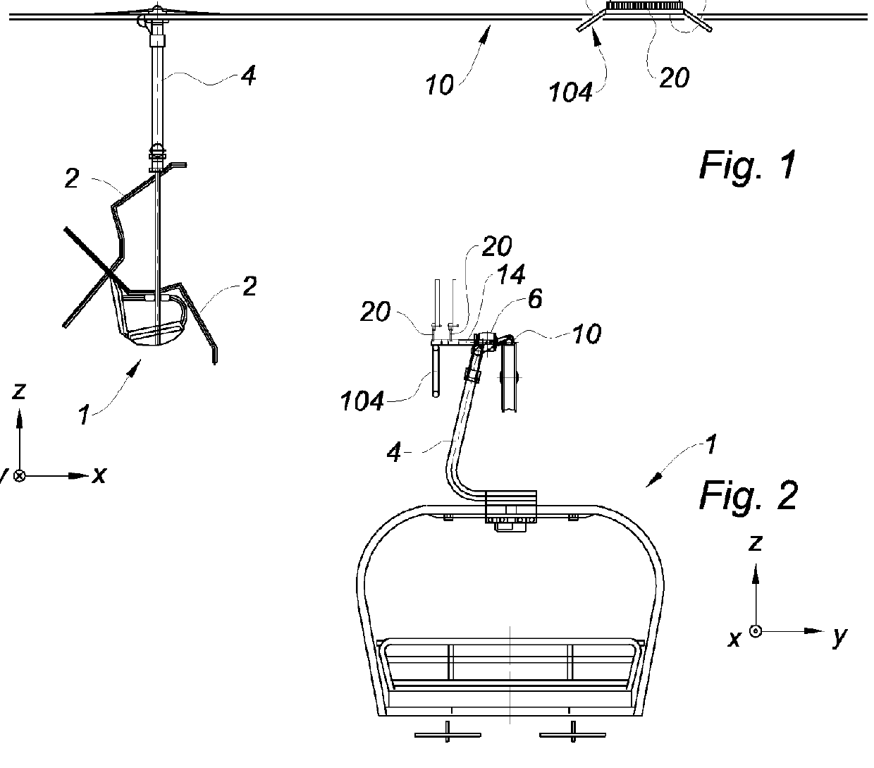
[0043]FIGS. 1 and 2 show a mechanical lift vehicle 1 according to an embodiment of the invention, in particular an aerial transport vehicle, in this case a mechanical lift seat. This mechanical lift seat can comprise a movable guard-rail 2 between a high position wherein the guard-rail 2 releases a space to allow passengers embarking or disembarking, and a low position wherein the guard-rail 2 forms an obstacle to prevent passengers from falling. High and low positions are simultaneously represented in FIG. 1.

[0044]It is to be specified that the description is carried out with respect to a Cartesian reference frame, visible in FIGS. 1 and 2, related to the mechanical lift vehicle 1, the X axis being orientated in a longitudinal direction of the mechanical lift vehicle 1, the Y axis being orientated in a transverse direction of the mechanical lift vehicle 1, and the Z axis being orientated in a vertical direction of the mechanical lift vehicle 1. Longitudinal, transverse or vertical,...


PUM


Abstract

The vehicle comprises (1) a suspension (4) presenting an upper end (6) from which is transversely extended a portion (8) of hanging to an aerial carrying and hauling cable (10), and a controller (12), to control a predetermined technical function. Moreover, the vehicle (1) comprises an offset arm (14), extending in a transverse plane, from one side of the upper end (6) opposite to that from which the hanging portion (8) is extended, the offset arm (14) presenting a proximal end arranged at the height of the upper end (6) and a distal end supporting the controller (12), an abutment member (16), and connecting means, connecting the proximal end of the offset arm (14) and the suspension (4), the connecting means enabling displacement of the offset arm (14) in the transverse plane.

Description

TECHNICAL FIELD[0001]The present invention concerns a mechanical lift vehicle and a mechanical lift installation comprising this vehicle.BACKGROUND[0002]Conventionally, a mechanical lift installation allows passengers, skiers or pedestrians, to ascend or to descend slopes. A mechanical lift installation includes generally two end stations, a station placed at the bottom of the slope and a station placed at the top of the slope. These end stations are connected by an aerial carrying and hauling cable which can form a closed loop. It is known to drive the cable through pulleys and to support it by means of pylons. Vehicles suspended from the cable allow transporting passengers from an end station to another.[0003]When the cable forms a closed loop, each end station may include an area for both embarking and disembarking passengers. The mechanical lift installation gives thus the possibility to transport simultaneously passengers ascending or descending the slope.[0004]Mechanical lift ...

Claims


Application Information

Patent Timeline
Patent Type & Authority Applications(United States)
IPC IPC(8): B61B12/00B61B11/00
CPCB61B11/00B61B12/002B61B12/06
Inventor CHEDAL, BORNU, YVES
Owner SOMMITAL
Why Eureka
Try Eureka