Supercharge Your Innovation With Domain-Expert AI Agents!

Remote plasma clean source feed between backing plate and diffuser

a plasma clean source and diffuser technology, applied in the direction of coatings, chemical vapor deposition coatings, chemistry apparatuses and processes, etc., can solve the problem that the clean plasma may generate undesired particles in the chamber

Inactive Publication Date: 2016-02-04
APPLIED MATERIALS INC
View PDF13 Cites 10 Cited by
  • Summary
  • Abstract
  • Description
  • Claims
  • Application Information

AI Technical Summary

Benefits of technology

The present patent describes an apparatus and method for cleaning a processing chamber using a remote plasma clean source. The remote plasma clean source delivers radicals from a remote plasma reactor to the chamber at a specific location between a gas distribution plate and a blocker plate. This technology allows for efficient cleaning of processing chambers, reducing downtime and improving overall production efficiency.

Problems solved by technology

The cleaning plasma may generate undesired particles in the chamber.

Method used


Image

  • Remote plasma clean source feed between backing plate and diffuser
  • Remote plasma clean source feed between backing plate and diffuser
  • Remote plasma clean source feed between backing plate and diffuser

Examples


Embodiment Construction

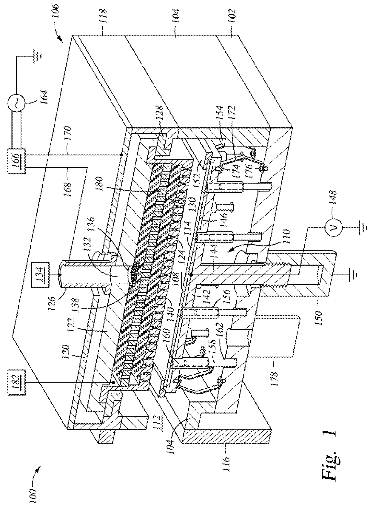
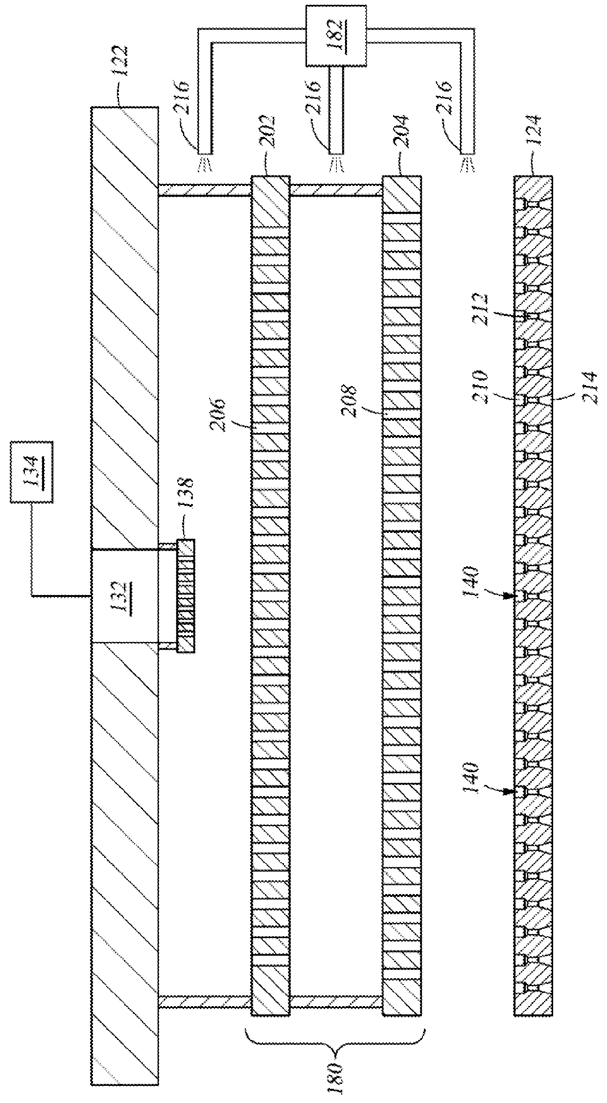
[0022]Embodiments of the present disclosure provide an apparatus having a remote plasma clean source in which the remote plasma clean source delivers radicals from the remotely generated plasma to the chamber at a location disposed between a backing plate and a diffuser.

[0023]FIG. 1 schematically illustrates a sectional side view of an apparatus including a plasma processing chamber 100 in accordance with one embodiment of the present disclosure. The plasma processing chamber 100 comprises a chamber body having a chamber bottom 102, sidewalls 104, and a lid assembly 106. The chamber bottom 102, sidewalls 104, and the lid assembly 106 define a processing volume 108. A substrate support assembly 110 is disposed in the processing volume 108. An opening 112 is formed through one side of the sidewalls 104. The opening 112 is configured to allow passage of substrate 114. A slit valve 116 is coupled to the sidewall 104 and configured to close the opening 112 during processing.

[0024]The lid...


PUM

PropertyMeasurementUnit
temperatureaaaaaaaaaa
diameteraaaaaaaaaa
diameteraaaaaaaaaa

Abstract

Embodiments of the present disclosure provide an apparatus having a remote plasma clean source in which the remote plasma clean source delivers radicals from the remotely generated plasma to the chamber at a location disposed between a backing plate and a diffuser.

Description

BACKGROUND[0001]1. Field[0002]Embodiments of the present disclosure generally relate to an apparatus having a remote plasma clean source coupled to the chamber such that the radicals from the plasma enter the chamber at a location disposed between the backing plate and the diffuser.[0003]2. Description of the Related Art[0004]Plasma enhanced chemical vapor deposition (PECVD) is generally employed to deposit thin films on substrates, such as semiconductor substrates, solar panel substrates, organic light emitting diode (OLED) substrates and liquid crystal display (LCD) substrates. PECVD is generally accomplished by introducing a precursor gas into a vacuum chamber having a substrate disposed on a substrate support.[0005]Uniformity is generally desired in the thin films deposited using a PECVD process. For example, a silicon nitride film is usually deposited using PECVD on a flat panel for a passivation or gate dielectric layer in a thin film transistor (TFT). The quality and uniformi...

Claims


Application Information

Patent Timeline
Patent Type & Authority Applications(United States)
IPC IPC(8): B08B7/00C23C16/44
CPCB08B7/0035C23C16/4405H01J37/32862H01J37/32357H01J37/3244H01J37/32853C23C16/345C23C16/452C23C16/45565C23C16/4586C23C16/505
Inventor KURITA, SHINICHITINER, ROBIN L.ANWAR, SUHAIL
Owner APPLIED MATERIALS INC
Features
  • R&D
  • Intellectual Property
  • Life Sciences
  • Materials
  • Tech Scout
  • Unparalleled Data Quality
  • Higher Quality Content
  • 60% Fewer Hallucinations
Learn More