Connector receptacle

Active Publication Date: 2016-02-04
ADVANCED CONNECTEK INC
View PDF4 Cites 1 Cited by
  • Summary
  • Abstract
  • Description
  • Claims
  • Application Information

AI Technical Summary

Benefits of technology

The technical effect of this patent is to provide a connector receptacle that protects the tongue portion of an insulating housing, making it rigid and preventing short circuit. A protective plate wraps around the tongue portion to avoid damage from external forces and includes a cutting notch to prevent power contacts from interfering with other components. This ensures safety and prevents short circuit.

Problems solved by technology

USB 2.0 has been mostly used as a transmission interface at present, and with the increasing popularity of digital multimedia and continuous expansion of transfer files, USB 2.0 cannot meet the market demand.
When the protective plate contacts the power contact, short circuit could be caused, and the connector may be overheating and breakdown.

Method used


Image

  • Connector receptacle
  • Connector receptacle
  • Connector receptacle

Examples


first embodiment

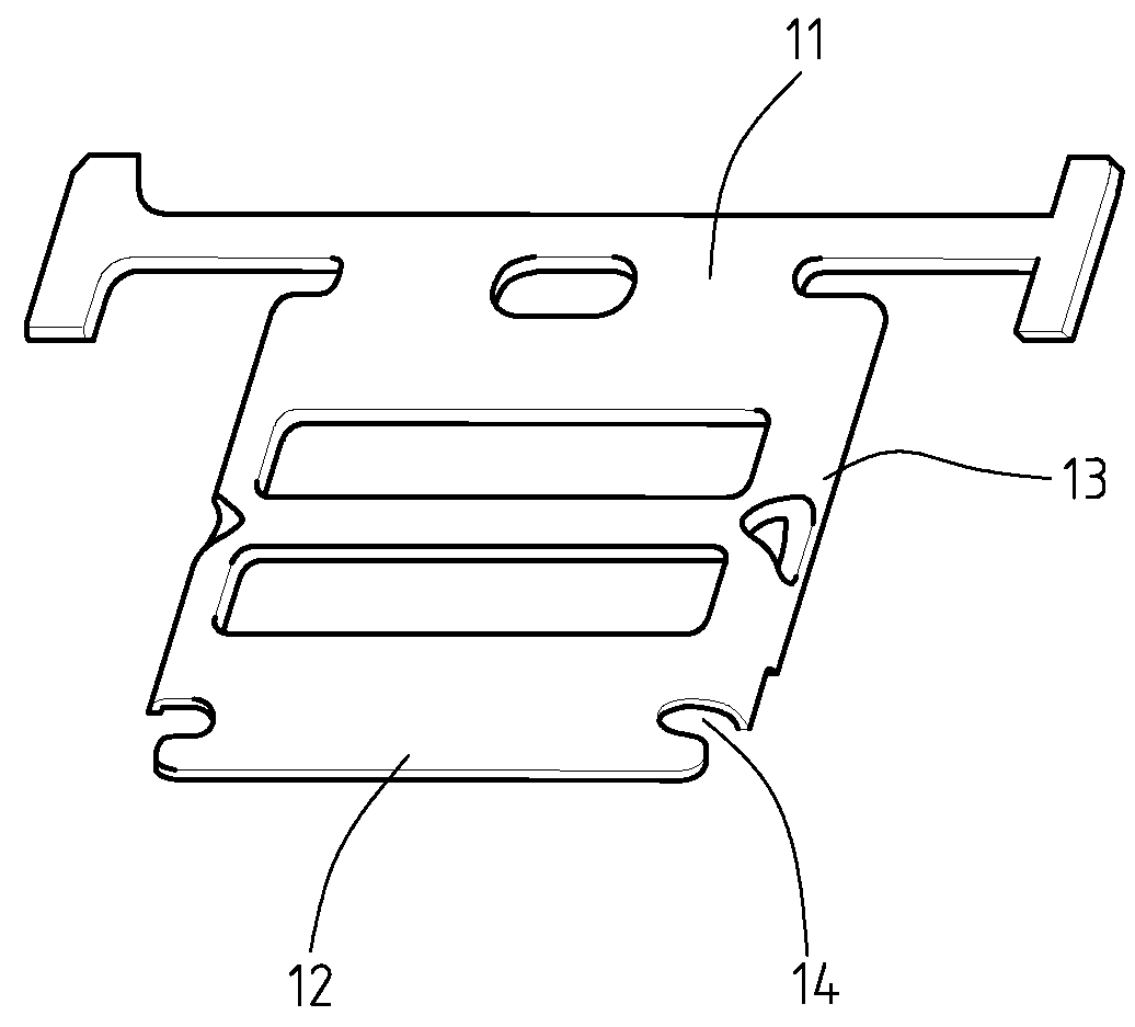
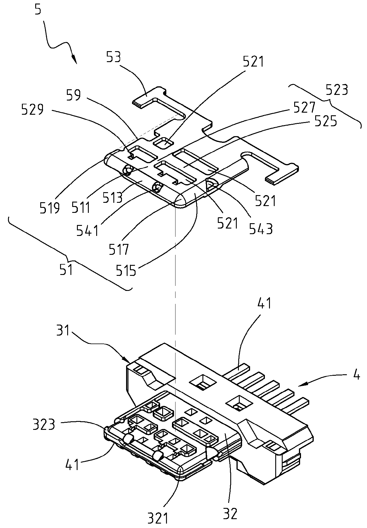
[0041]In the first exemplary embodiment according to the instant disclosure, The planar main portion 51 includes a second connecting section 519. The second connecting section 519 covers another corner 323 formed by meeting of the front surface and the side surfaces of the tongue portion 32. The cutting notch 59 extends from the second connecting section 519 to the connecting arm portions 53 at the same side of the second connecting section 519. In the first embodiment, most portions of one of two lateral sides of the planar main portion 51 is removed to form the cutting notch 59. Therefore, the power contact 41 and the protective plate 5 do not contact each other while a plug is plugged in the connector receptacle 2.

[0042]The planar section 511 further includes at least two first openings 521, and each two of the first openings 521 are separated by a bridge section 523. In the first exemplary embodiment according to the instant disclosure, as shown in FIG. 2-5, the planar main port...

second embodiment

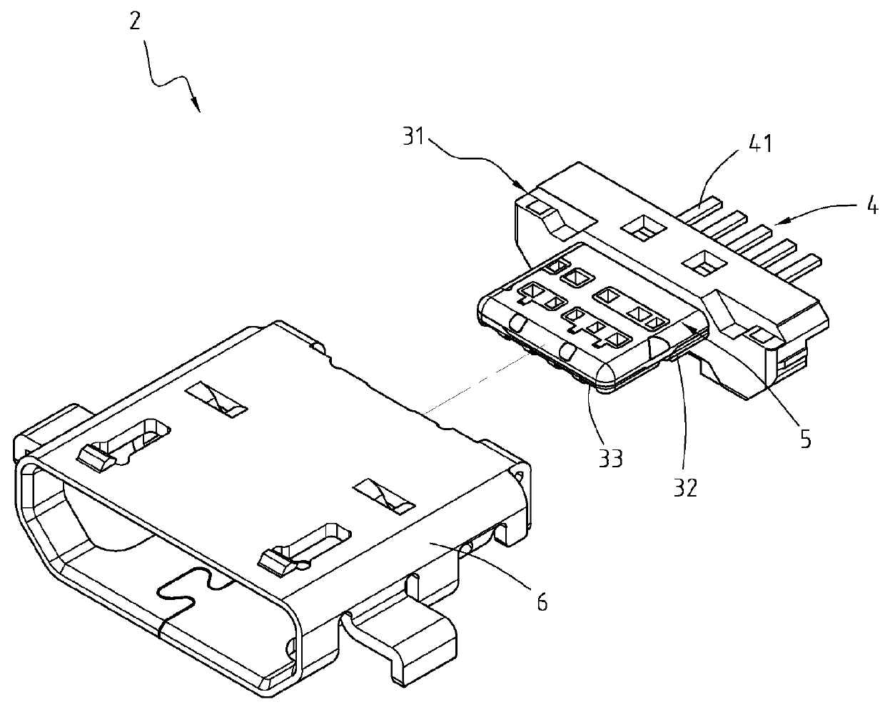
[0044]Referring to FIG. 6, FIG. 7, FIG. 8, and FIG. 9, FIG. 6 is a partly exploded perspective view of a connector receptacle formed in a second exemplary embodiment according to the instant disclosure, FIG. 7 is a partly exploded perspective view of FIG. 6 formed in the second exemplary embodiment according to the instant disclosure, where the metallic shell is omitted, FIG. 8 is another partly exploded perspective view of FIG. 6 formed in the second exemplary embodiment according to the instant disclosure, where the metallic shell is omitted, and FIG. 9 is a perspective cross-sectional view of the connector receptacle formed in the second exemplary embodiment according to the instant disclosure. The second exemplary of the instant disclosure provides a connector receptacle 2 which includes an insulating housing 3, a plurality of contacts 4, a protective plate 7, and a metallic shell 6. In the second embodiment, the connector receptacle 2 is a micro USB connector receptacle.

[0045]T...


PUM


Abstract

A connector receptacle includes an insulating housing, a plurality of contacts, a protective plate, and a metallic shell. The insulating housing includes a base portion and a tongue portion extending from the base portion. The tongue portion defines a plurality of receiving slots through the base portion. The contacts are inserted into the receiving slots, and a power contact exists among the contacts. The protective plate includes a planner main portion and two connecting arm portions. The planar main portion is disposed on the tongue portion, and includes a planar section, a front section, a side section, and a connecting section. One lateral side of the planar section is a cutting notch exposing parts of the tongue portion which corresponds to the power contact. The cutting notch prevents the power contact and the protective plate from contacting while connecting with a plug, so as to secure the safety.

Description

CROSS-REFERENCES TO RELATED APPLICATIONS[0001]This application is a continuation-in-part (CIP) of application Ser. No. 14 / 045,067, filed on Oct. 3, 2013 with claiming foreign priority of TW 101219238. The prior application is herewith incorporated by reference in its entirety.BACKGROUND[0002]1. Technical Field[0003]The instant disclosure relates to a connector receptacle, and more particularly to a connector receptacle capable of protecting a tongue portion of an insulating housing, enforcing rigidity of the tongue portion of the insulating housing, and preventing the connector receptacle from breakdown.[0004]2. Related Art[0005]A Universal Serial Bus (USB) connector, generally called a USB connector, has been widely used in signal transmission on various occasions due to its characteristics such as plug and play and fast transmission speed, and with the development of the USB connector, people have more demands for the transmission speed and stability.[0006]USB 2.0 has been mostly ...

Claims


Application Information

Patent Timeline
IPC IPC(8): H01R24/60
CPCH01R2107/00H01R24/60H01R12/725H01R13/405H01R13/6581H01R24/62
Inventor CHIEN, MIN-LUNGCHANG, MING-YUNGWONG, YUN-JHONGTSAI, CHENG-CHE
Owner ADVANCED CONNECTEK INC
Why Eureka
Try Eureka