Cement kiln power material scattering device and cement kiln with same

A technology of a material spreading device and a power device, applied in the field of cement kilns, can solve the problems of no effective material control, material short circuit, poor material flow control ability, etc., to achieve contact and mixed contact, improve heat exchange efficiency, and ensure normal production. Effect

Pending Publication Date: 2019-10-01
广州泰科节能环保科技有限公司
View PDF0 Cites 2 Cited by
  • Summary
  • Abstract
  • Description
  • Claims
  • Application Information

AI Technical Summary

Problems solved by technology

However, the material flow control ability of this kind of material spreading device is poor, and there is no effective control on the material. The material is completely dispersed by natural flow and splashing. It is difficult to ensure that the material is fully and evenly dispersed and fully contacted with the hot air to exchange heat. Inhomogeneous mixing with high temperature gas leads to low heat transfer efficiency of the system
[0004] In addition, due to the fast downstroke speed and strong downstroke force of the strands of materials under the action of gravity, it is difficult to suspend all the materials by the high-temperature gas, so some materials often collapse directly, and the so-called "material" "short circuit", causing the problem that the entire cement kiln system cannot be produced normally

Method used


Image

  • Cement kiln power material scattering device and cement kiln with same
  • Cement kiln power material scattering device and cement kiln with same
  • Cement kiln power material scattering device and cement kiln with same

Examples


Embodiment 1

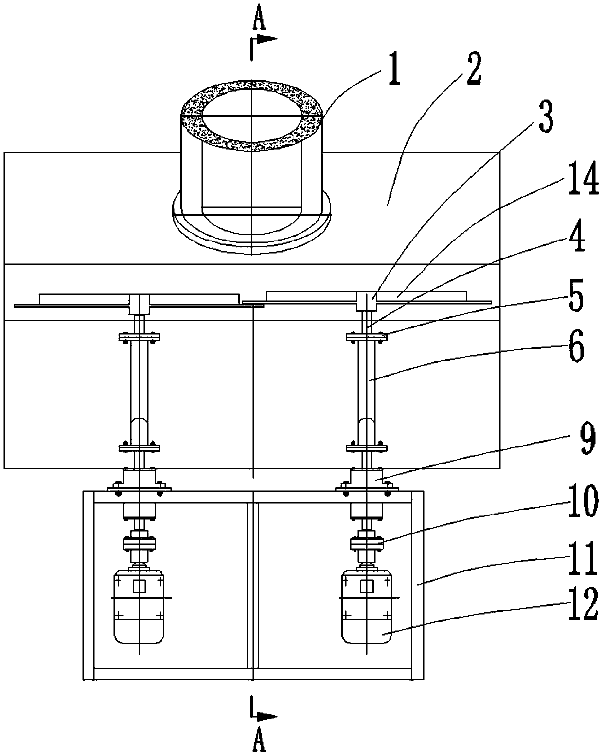
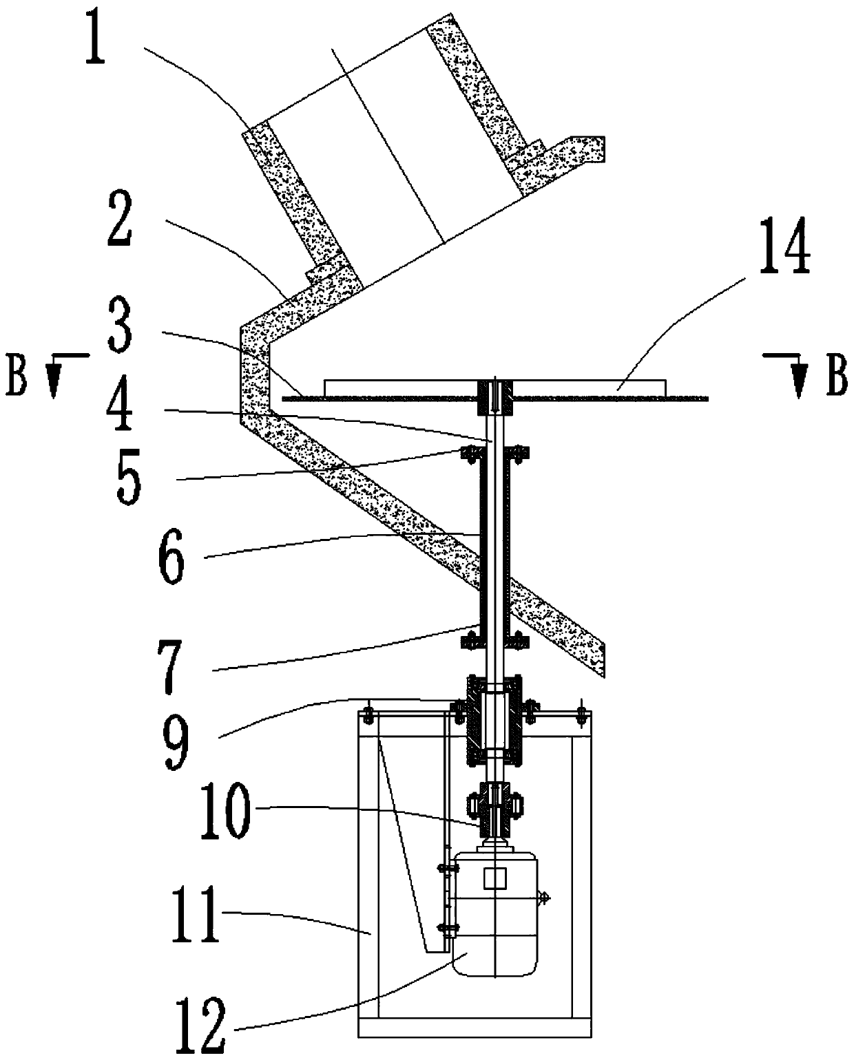
[0040] A power spreading device for cement kiln, which can disperse the material very evenly, cover the high-temperature gas flow well, and realize the full mixing and contact between the low-temperature material and the high-temperature gas, thereby greatly improving the heat exchange efficiency of the system, such as figure 1 , figure 2 , image 3 , Figure 4 As shown, specifically set to the following structure:

[0041] It includes a material spreading box 2. The front side of the material spreading box 2 forms an opening, and the upper part has a material opening for connecting with the material discharge pipe 1 for discharging. The opening of the material spreading box 2 is used to connect with the outlet of the cyclone. The side wall of the pipe 15 is fixed and communicated with the inside of the cyclone outlet pipe 15 so as to pass the material scattered by the spreading plate 3 .

[0042] Two groups of spreading discs 3 are installed on the inner side of the sprea...

Embodiment 2

[0048] This embodiment is further optimized on the basis of the above-mentioned embodiments, further to better realize the present invention, especially adopt the following configuration structure:

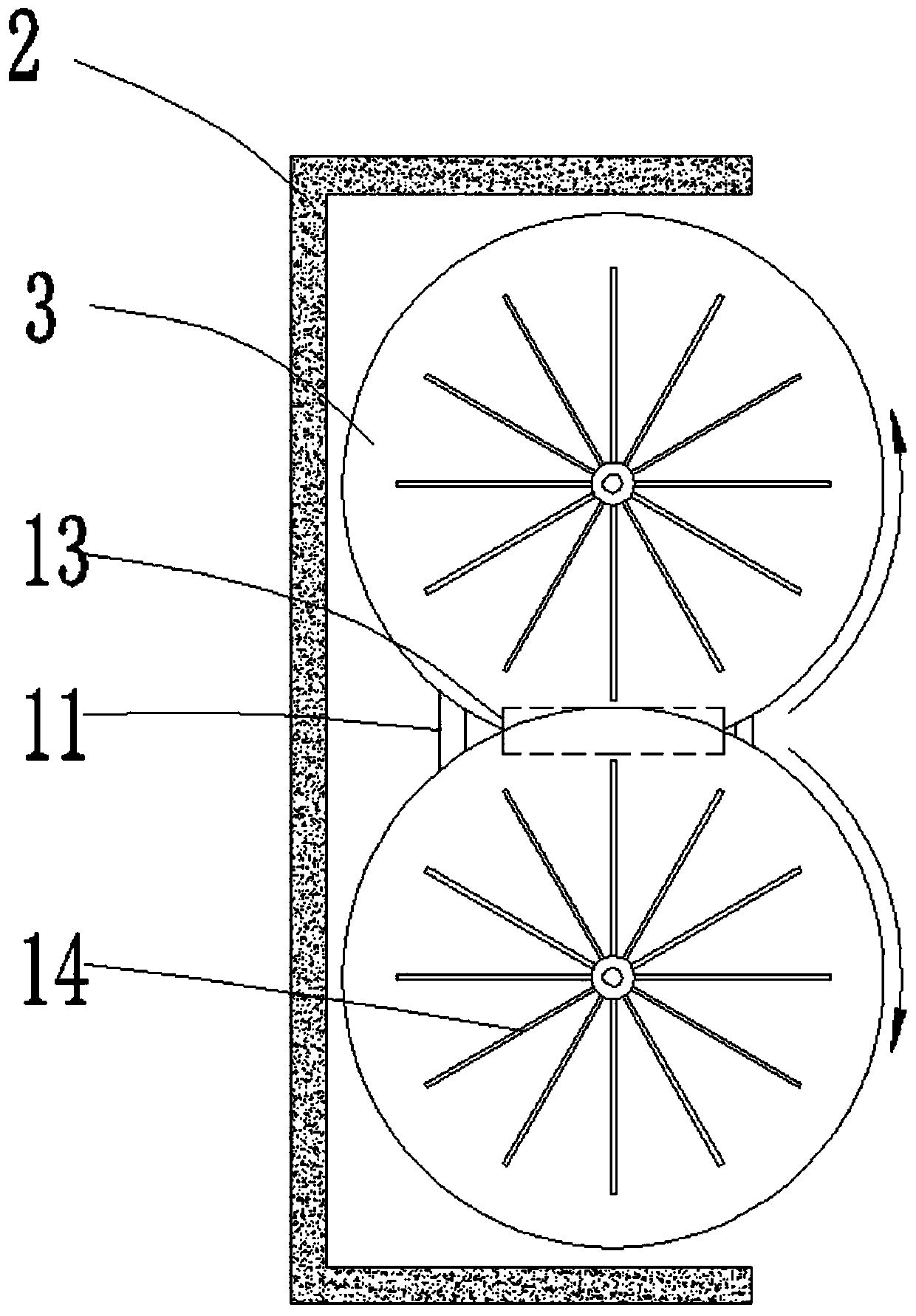
[0049] The two groups of spreading discs 3 are dislocated up and down relative to each other, and the two groups of spreading discs 3 have overlapping areas 13 in the vertical direction, image 3 The closed figure represented by the dotted line in the middle is the superposition area 13, and the axis of the feeding port intersects with the superposition area 13. In this way, the material will not completely pass between the two sets of spreading discs 3 , but will fall to the overlapping area 13 and be thrown to the opening of the spreading box 2 by the spreading discs 3 .

Embodiment 3

[0051] This embodiment is further optimized on the basis of the above-mentioned embodiments, further to better realize the present invention, especially adopt the following configuration structure:

[0052] The top surface of every group of spreading disc 3 is all provided with at least one spreading bar 14, and spreading bar 14 is a straight plate, and the bottom surface of spreading bar 14 is connected with the disk surface of spreading disc 3 and is welded and fixed on the spreading bar. On the top surface of the disc 3 , the length direction of the spreading bar 14 is consistent with the radial direction of the corresponding spreading disc 3 . The material spreading bar 14 is used to forcibly disperse the material to improve the dispersing effect without causing excessive material accumulation and the material spreading plate 3 .

[0053] When there are multiple spreading strips 14 in each set of spreading trays 3 , the spreading strips 14 on the top surface of each set of...


PUM

PropertyMeasurementUnit
angleaaaaaaaaaa
heightaaaaaaaaaa

Abstract

The invention provides a cement kiln power material scattering device and a cement kiln with the same and relates to the field of cement kiln equipment. The problems that in the prior art, materials are preheated unevenly, and direct material falling is likely to happen are solved. The power material scattering device comprises a material scattering box, an opening is formed in the front side of the material scattering box, and a discharging port is formed in the upper portion of the material scattering box. Two sets of material scattering discs with power devices are installed on the inner side of the material scattering box, and the two sets of material scattering discs are oppositely distributed in a left-right mode, can revolve around the central axes, are located below the dischargingport of the material scattering box to be used for receiving material and can scatter the materials towards the opening of the material scattering box. The cement kiln adopts the power material scattering device, high heat exchange efficiency between materials and hot gas is achieved, and the material direct-falling problem can be avoided, materials can be scattered very evenly and well cover high-temperature gas flow, fully mixing and contact of low-temperature materials and high-temperature gas can be achieved, and thus the heat exchange efficiency of the system can be greatly improved.

Description

technical field [0001] The invention relates to the field of cement kiln equipment, in particular to a power spreading device for a cement kiln and a cement kiln using the power spreading device. Background technique [0002] At present, in the world's most common new-type dry-process external decomposition cement kiln, the material preheating and decomposition system composed of multi-stage cyclone and decomposition furnace is widely used for rapid preheating and decomposition of low-temperature materials, and the flow direction of materials is: Low-temperature material feeding point—first-stage cyclone—second-stage cyclone—third-stage cyclone—fourth-stage cyclone—calciner—fifth-stage cyclone—rotary kiln, where the flow direction of high-temperature gas is: rotary kiln + third air duct — Calciner — fifth-stage cyclone — fourth-stage cyclone — third-stage cyclone — second-stage cyclone — first-stage cyclone — discharge preheater system. [0003] The spreading devices used i...

Claims


Application Information

Patent Timeline
Patent Type & Authority Applications(China)
IPC IPC(8): F27D3/18
CPCF27D3/18
Inventor 王志宏
Owner 广州泰科节能环保科技有限公司
Why Eureka
Try Eureka