Battery device

Inactive Publication Date: 2005-08-16
LAN HSIN CHANG +1
View PDF2 Cites 0 Cited by
  • Summary
  • Abstract
  • Description
  • Claims
  • Application Information

AI Technical Summary

Benefits of technology

[0007]One aspect of an exemplary embodiment according to the present invention is to provide a bi-electrode structure of a battery. The bi-electrode structure includes a positive electrode and a negative electrode respectively combining with a substrate to simplify the manufacturing process of the battery.
[0008]The present invention provides a bi-electrode structure that includes a substrate, a positive electrode and a negative electrode. The positive electrode and the negative electrode are respectively formed on different sides of the substrate. To improve the conductivity, the positive electrode further includes a first metal layer formed on the substrate and a positive material layer formed on the first metal layer. Similarly, the negative electrode further includes a second metal layer formed on the other side of the substrate and a negative material layer formed on the second metal layer. The substrate is made of an insulating material to prevent the positive electrode and the negative electrode from short circuiting. A separator is disposed either on the positive electrode or the negative electrode to avoid short circuiting before the bi-electrode structure is rolled or stacked and placed in a case. Then, an electrolyte is injected into the case to make a battery.

Problems solved by technology

However, it is difficult to roll these overlapping plates during the manufacturing process of the battery.
Moreover, it may even cause short circuit at the edges of these plates when the worst case happens.

Method used


Image

  • Battery device
  • Battery device
  • Battery device

Examples


Embodiment Construction

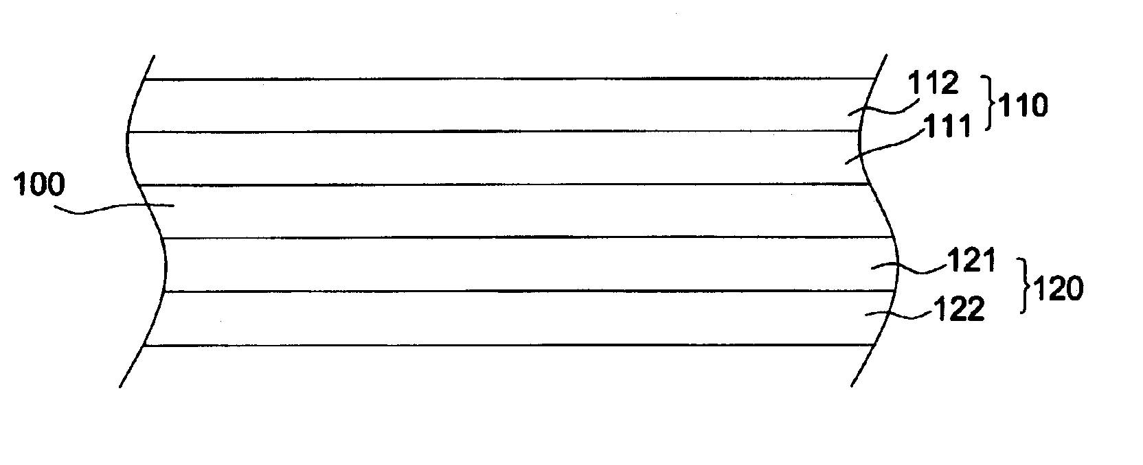
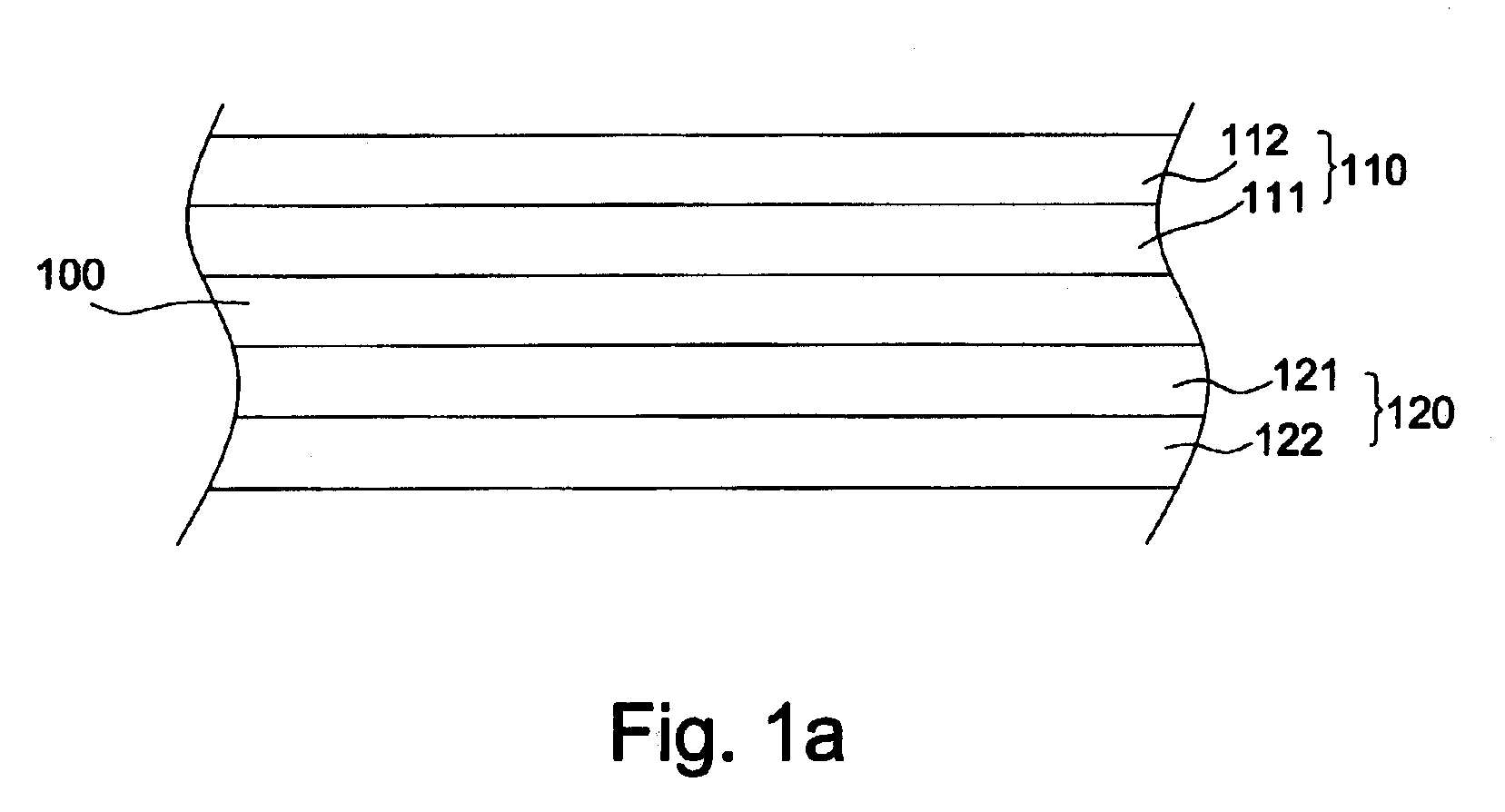
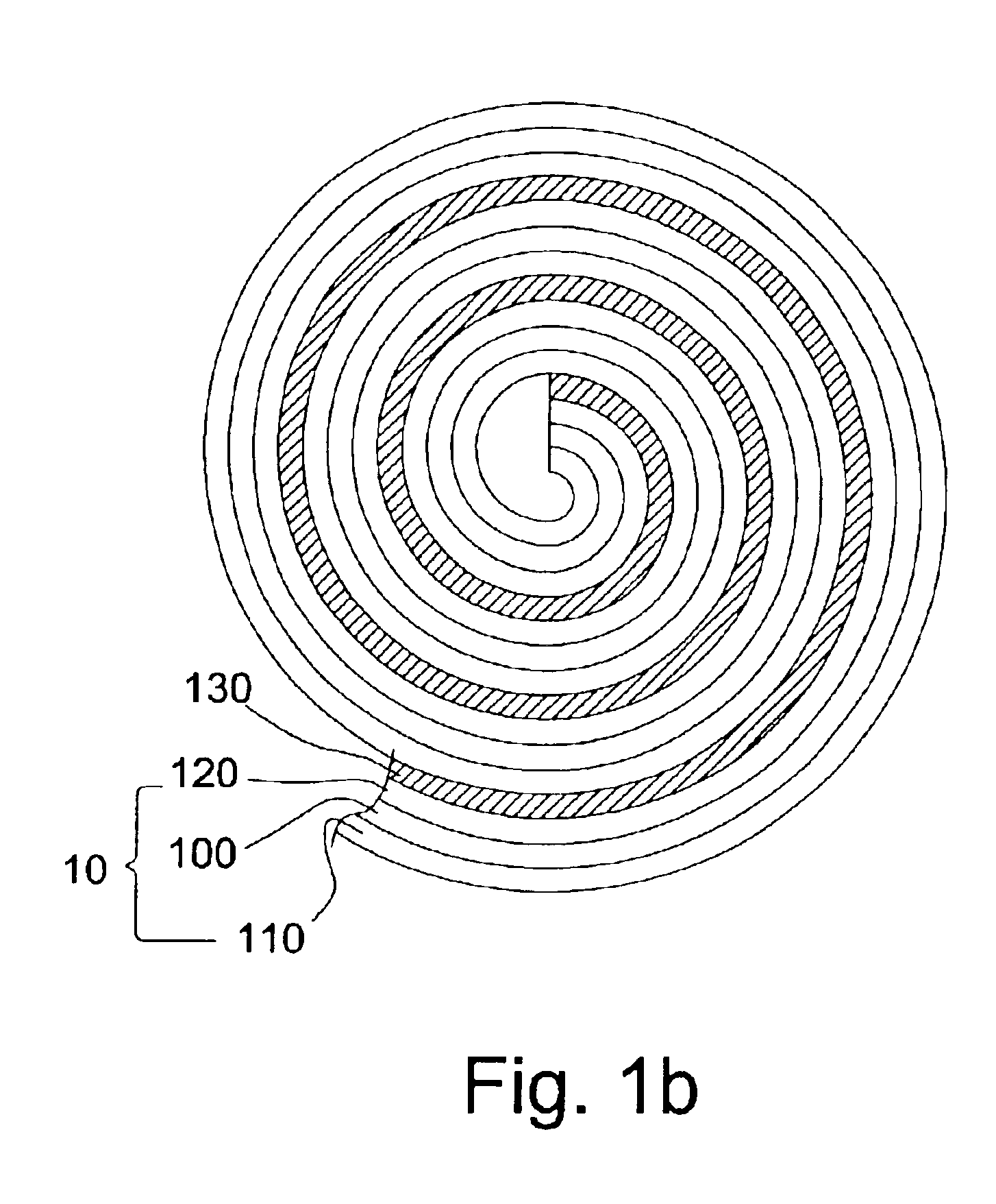
[0015]The present invention discloses a bi-electrode structure 10 for making a battery. FIG. 1a is a cross-section view of the bi-electrode structure 10 according to an exemplary embodiment. The bi-electrode structure 10 includes a substrate 100, a positive electrode 10 formed on one side of the substrate 100 and a negative electrode 120 formed on the other side of the substrate 100. The substrate 100 insulates the positive electrode 110 and the negative electrode 120 from short circuiting. In addition, the substrate 100 supports the positive electrode 110 and the negative electrode 120 to form a bi-electrode structure 10.

[0016]To improve the conductivity, the positive electrode 110 includes a first metal layer 111 and a positive material layer 112. The first metal layer 111 is formed on the substrate 100 and the positive material layer 112 is formed on the first metal layer 111. Similarly, the negative electrode 120 includes a second metal layer 121 and a negative material layer 12...


PUM


Abstract

The present invention includes a bi-electrode structure including a substrate, a positive electrode, and a negative electrode. The positive electrode and the negative electrode are respectively formed on different sides of the substrate. The substrate is to support and insulate the positive electrode and the negative electrode. To improve the conductivity, the positive electrode has a first metal layer and a positive material layer Similarly, the negative electrode has a second metal layer and a negative material layer. After covering with a separator on either the positive electrode or the negative electrode, the bi-electrode structure is rolled to form a battery with cylindrical shape or stacked up to form a prismatic battery.

Description

[0001]This application claims priority of Taiwan Patent Application No. 091115198 filed on Jul. 09, 2002.FIELD OF INVENTION[0002]The present invention relates to an electrode plate structure of a battery.BACKGROUND OF THE INVENTION[0003]Recently, the trends for electronic equipment, such as mobile phones, digital cameras and personal digital assistant (PDA), etc. are toward thinner, lighter, and smaller equipment. The structure of a battery, which is used in much electronic equipment, then inevitably decides the weight, energy density, and volume of the battery.[0004]The traditional electrode structure of a battery as shown in FIG. 2a and FIG. 2b includes a positive electrode 30, a separator 31, a negative electrode 32 and a separator 33 overlapping to form an electrode group. Then, at least one of the electrode group is rolled to form a circle, an ellipse or a spiral, as shown in FIG. 2a, within a cylindrical or prismatic case (not shown) for making a battery. Alternatively, a plur...

Claims


Application Information

Patent Timeline
IPC IPC(8): H01M4/02H01M10/04H01M2/02
CPCH01M4/02H01M10/044H01M2/0217H01M2004/029H01M50/103Y02E60/10Y02P70/50
Inventor LAN, HSIN-CHANGLAN, WEI-HSIN
Owner LAN HSIN CHANG
Why Eureka
Try Eureka