Intelligent gate drive unit

Active Publication Date: 2016-02-04
K B ELECTRONICS INC
View PDF9 Cites 13 Cited by
  • Summary
  • Abstract
  • Description
  • Claims
  • Application Information

AI Technical Summary

Benefits of technology

[0007]It may e.g. be an object of the present invention to provide measurements facilitating reduction of unnecessary safety margins when controlling power modules. This is accomplished by an intelligent gate drive unit for controlling one or more semiconductor switches of one or more power modules, the intelligent gate

Problems solved by technology

In other words overload capabilities are limited by predefined cur

Method used


Image

  • Intelligent gate drive unit
  • Intelligent gate drive unit
  • Intelligent gate drive unit

Examples


Embodiment Construction

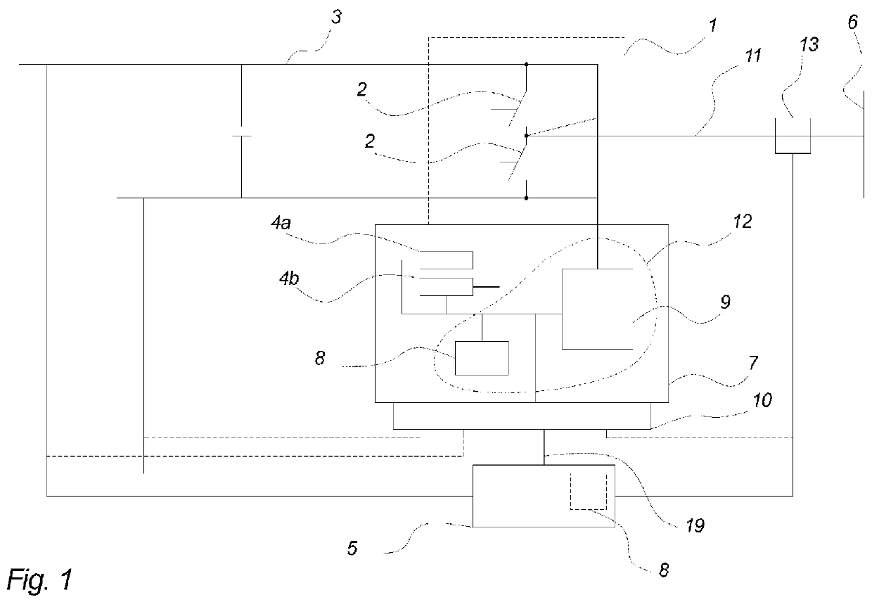
[0071]FIG. 1 illustrates a part of a converter which is connecting a renewable power generating unit such as a wind turbine to the utility grid 6. Such converter may comprise a generator / machine side inverter (not illustrated) and a grid side inverter which is illustrated by a power module comprising two semiconductor switches 2. The generator side inverter and the grid side inverter are connected to each other by a DC-link 3. Each of the inverters may comprise one or more power modules comprising one or more switches.

[0072]The power module is controlled so as to shape the power produced by the renewable power generating unit to comply with predefined requirements e.g. in relation to the grid frequency and voltage. The semiconductor switches 2 are typically Insulated Gate Bipolar Transistors (IGBTs) but other types of semiconductor switches 2 could also be used (such as e.g. IGCT, Thyristors, GTO, Silicon Carbide switches, etc.). The semiconductor switches 2 may be grouped together ...


PUM


Abstract

An intelligent gate drive unit and related method for controlling one or more semiconductor switches of one or more power modules, the intelligent gate drive unit comprises at least a gate driver and an analog measuring circuit, wherein the gate driver facilitates control of the one or more semiconductor switches and wherein the analog measuring circuit facilitates measuring the switch voltage when the one or more semiconductor switches are in a conducting mode.

Description

FIELD OF INVENTION[0001]The invention relates to an intelligent gate drive unit for controlling a power module comprising one or more semiconductor switches.BACKGROUND OF THE INVENTION[0002]Power modules are known in the art and used as switches or rectifiers in power electronic circuits for controlling the power flow from a generator of a renewable power generating unit to the electrical grid.[0003]The application in which the power modules are used may produces power and the closer to design limits the more power may be produced.[0004]Such power modules can be protected by the way they are controlled i.e. most likely the lifetime of a power module which has been controlled close to its design limits are shorter than a power module which has been controlled according to an operation margin or safety margin which is lower than the design limit. In other words overload capabilities are limited by predefined current-time pattern which means large operation margin for overload.[0005]In...

Claims


Application Information

Patent Timeline
IPC IPC(8): H03K17/082H02M1/08H02M1/32H02M7/44H03K17/687
CPCH02M7/44H02M1/08H03K17/6877H03K2017/0806H03K17/0822H02M1/32
Inventor RANNESTAD, BJORN
Owner K B ELECTRONICS INC
Why Eureka
Try Eureka