Chilled vehicle fuel storage tank

a fuel storage tank and cold-fired technology, which is applied in the direction of lighting and heating equipment, transportation and packaging, heating types, etc., can solve the problems of more prone to damage of tubing, and achieve the effects of reducing heat transfer, preventing condensation, and improving thermal efficiency of methods and systems

Active Publication Date: 2016-02-11
BILLS ANTWANETTE +1
View PDF1 Cites 3 Cited by
  • Summary
  • Abstract
  • Description
  • Claims
  • Application Information

AI Technical Summary

Benefits of technology

[0017]Optionally, the tubing is enclosed by an insulating wrap or shell that covers the exterior of the fuel tank. The insulating wrap or shell improves the thermal efficiency of the method and system by reducing the heat transfer between the fuel storage system and the ambient environment. In order to prevent condensation between the optional insulat...

Problems solved by technology

However, the tubing will be more prone to damage when placed on the bottom of the fuel tank, ...

Method used


Image

  • Chilled vehicle fuel storage tank
  • Chilled vehicle fuel storage tank
  • Chilled vehicle fuel storage tank

Examples


Embodiment Construction

[0026]The following descriptions are not meant to limit the invention, but rather to illustrate its general principles of operation. Examples are illustrated with the accompanying drawings. A variety of drawings are offered, showing various aspects of the invention.

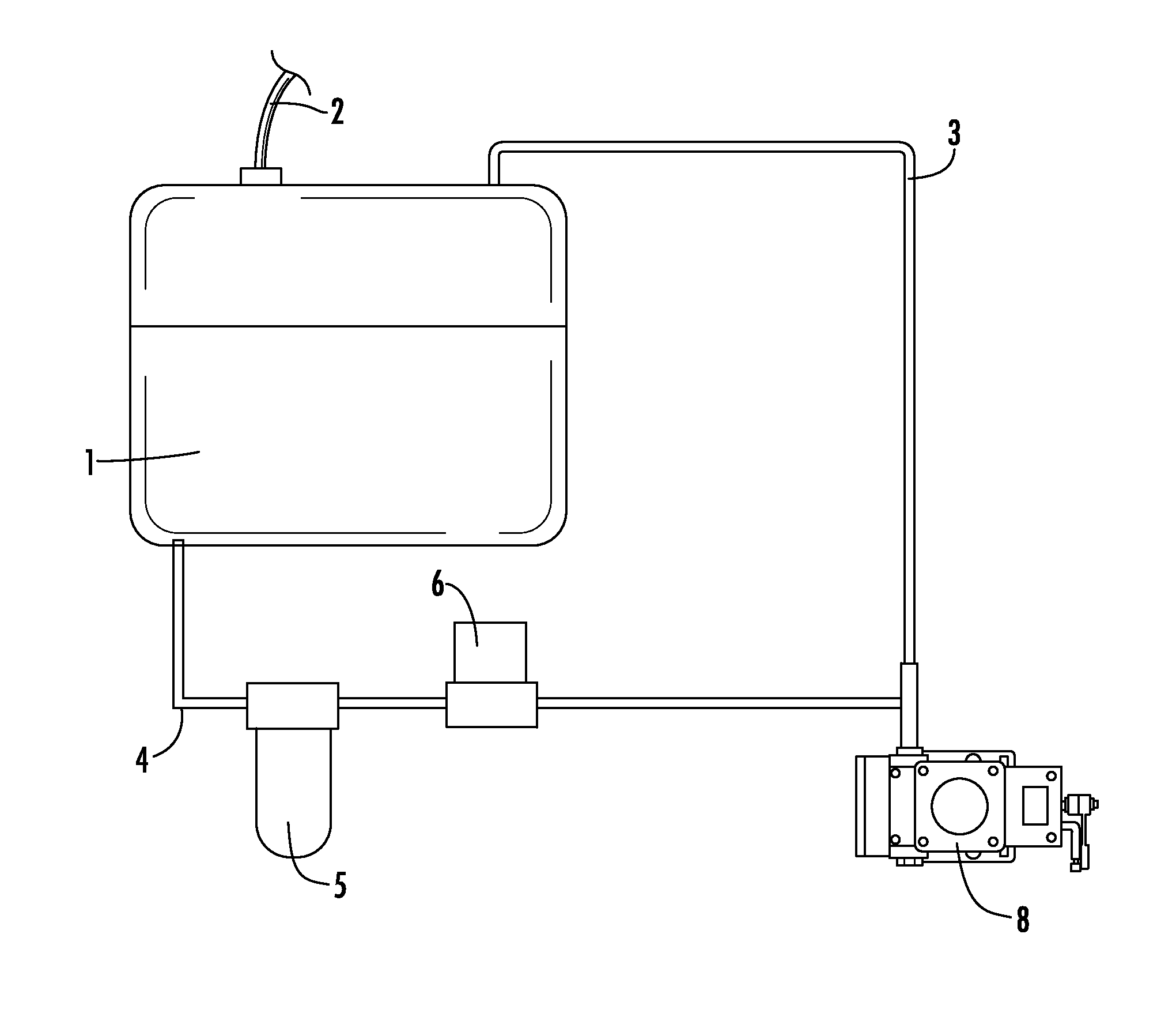
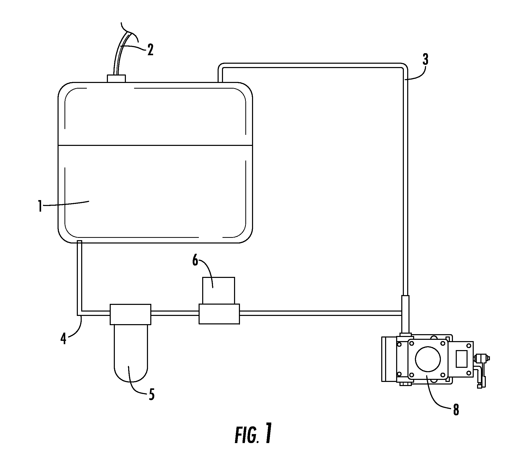
[0027]FIG. 1 shows a generic vehicle fuel storage and distribution system, including a fuel tank 1, a fill tube 2, a fuel line 4, a fuel filter 5, a fuel pump 6, and an injector 8. Fuel that is not used by the injector 8 is returned to the fuel tank 1 via the return fuel line 3.

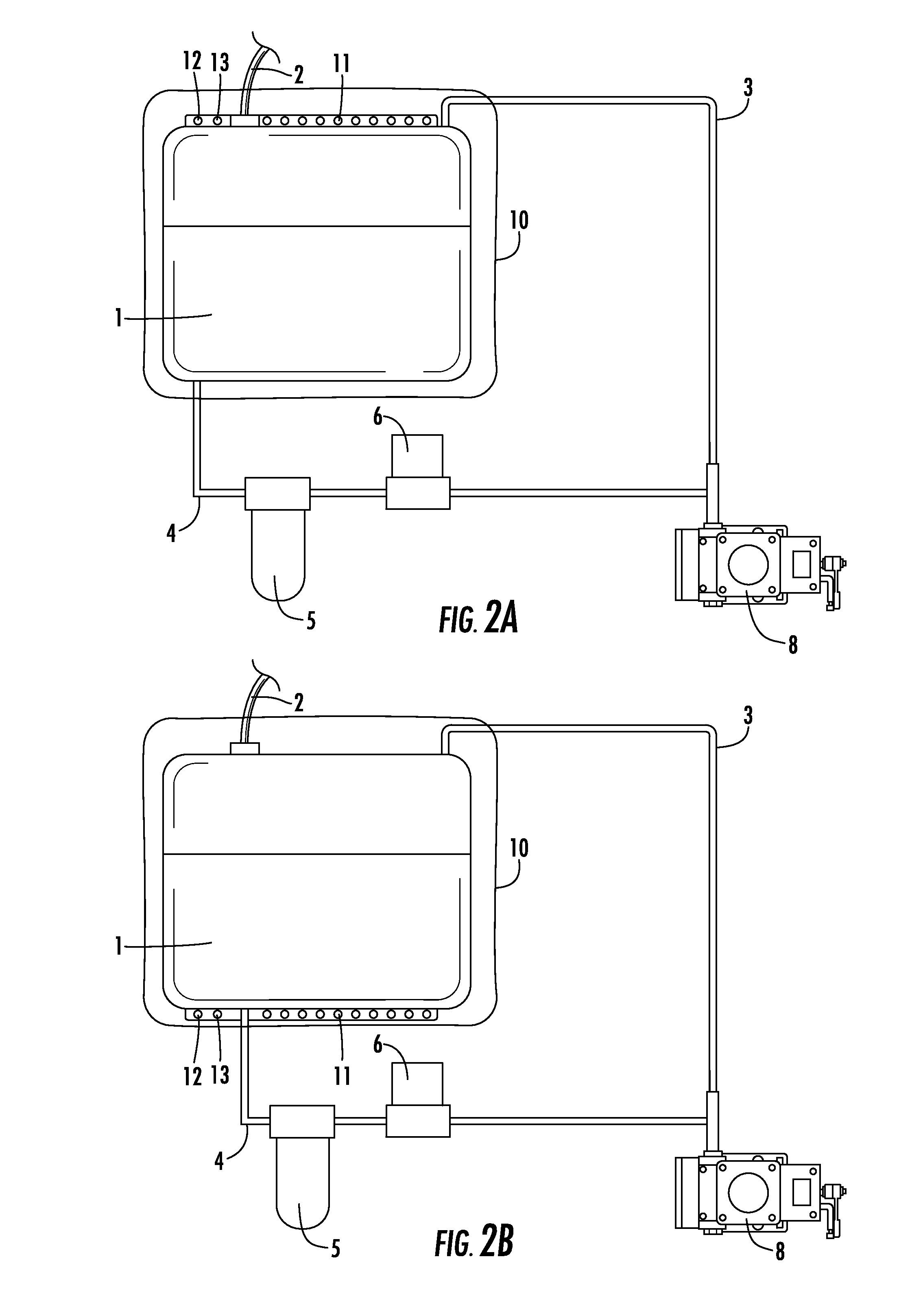
[0028]FIG. 2a shows a generic vehicle fuel storage and distribution system with the present invention included. The standard elements from FIG. 1 are present: a fuel tank 1, a fill tube 2, a fuel line 4, a fuel filter 5, a fuel pump 6, an injector 8, and a return fuel line 3. In addition, on the top of the tank, there is bulk tubing 11, with an intake 12 and an outflow 13. The tubing 11 and fuel tank 1 are wrapped in a insulating wrap 10. In this e...


PUM


Abstract

A method and system for cooling the fuel contained in the fuel storage tank of motor vehicles using internal combustion engines. The method and system uses tubing in intimate contact with the exterior of the fuel tank to cool the fuel tank. The method and system may optionally employ an insulating wrap or shell to improve thermal efficiency.

Description

FIELD OF INVENTION[0001]This invention relates to internal combustion engines. Specifically, this invention relates to cooling the fuel storage tank for an internal combustion engine.BACKGROUND OF INVENTION[0002]The internal combustion engine (ICE) is a self-contained powerplant in which a vapor consisting of a fossil fuel (gasoline or diesel) and oxygen is ignited in a sealed combustion chamber. The ICE has revolutionized society, leading the unprecedented industrialization of the western world in the 20th century. Now, ICEs are ubiquitous, being the favored power source for automobiles, light trucks, and heavy trucks.[0003]Between now and the year 2020, it is estimated that the total worldwide car parc (total registered light vehicles) will grow from approximately 620 million units to almost 1 billion units. During that same time, the annual worldwide new vehicles sales will grow from approximately 80 million to 115 million units per year. This explosion in vehicle ownership will ...

Claims


Application Information

Patent Timeline
IPC IPC(8): B60K15/03
CPCB60K15/03006B60K2015/03414B60K2015/03493B60K15/03177B60H1/00271B60K15/03
Inventor BILLS, ANTWANETTEBILLS, ANTHONY
Owner BILLS ANTWANETTE
Why Eureka
Try Eureka