Device using a piezoelectric element and method for manufacturing the same

Active Publication Date: 2016-02-11
ROHM CO LTD
View PDF4 Cites 21 Cited by
  • Summary
  • Abstract
  • Description
  • Claims
  • Application Information

AI Technical Summary

Benefits of technology

The patent describes a piezoelectric element that has a movable film that can be easily deformed. By making the piezoelectric film easily deformable, the displacement of the movable film can be increased. To protect the piezoelectric film, an aluminum film is used as a hydrogen barrier film. The patent also describes a device made using this piezoelectric element where peeling-off of the upper electrode does not occur during use. The technical effects of the design include a larger displacement of the movable film and improved piezoelectric characteristics.

Problems solved by technology

It was found that with the arrangement trial-manufactured by the inventor, there is a possibility of peeling off of the upper electrode.
The hydrogen barrier film formed by the sputtering method is thin in film thickness at the side surface of the piezoelectric element and therefore is not necessarily sufficient in coverage.
Also, the hydrogen barrier film is damaged during the patterning of the interlayer insulating film below the wiring connected to the upper electrode.

Method used


Image

  • Device using a piezoelectric element and method for manufacturing the same
  • Device using a piezoelectric element and method for manufacturing the same
  • Device using a piezoelectric element and method for manufacturing the same

Examples


Embodiment Construction

[0120]Preferred embodiments of a first invention to a fourth invention shall now be described in detail with reference to the attached drawings.

[0121][1] First Invention

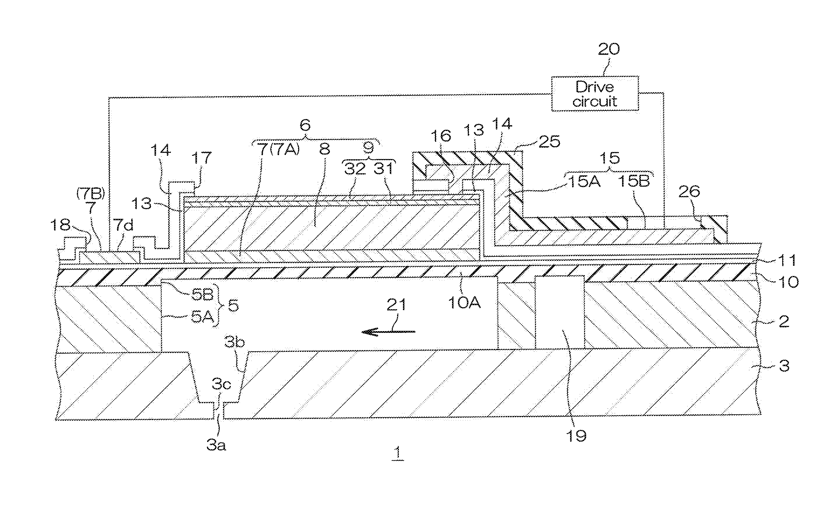
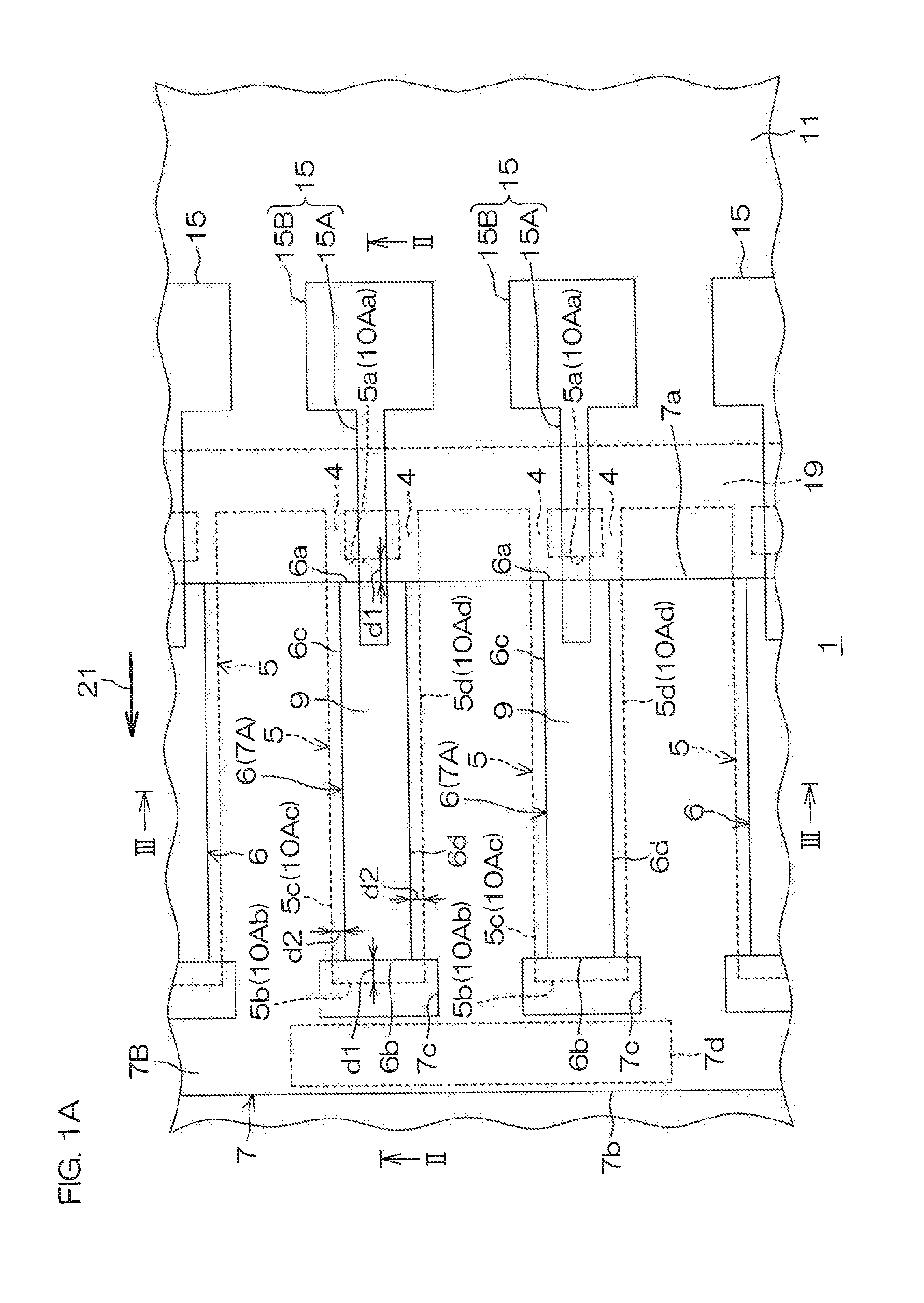
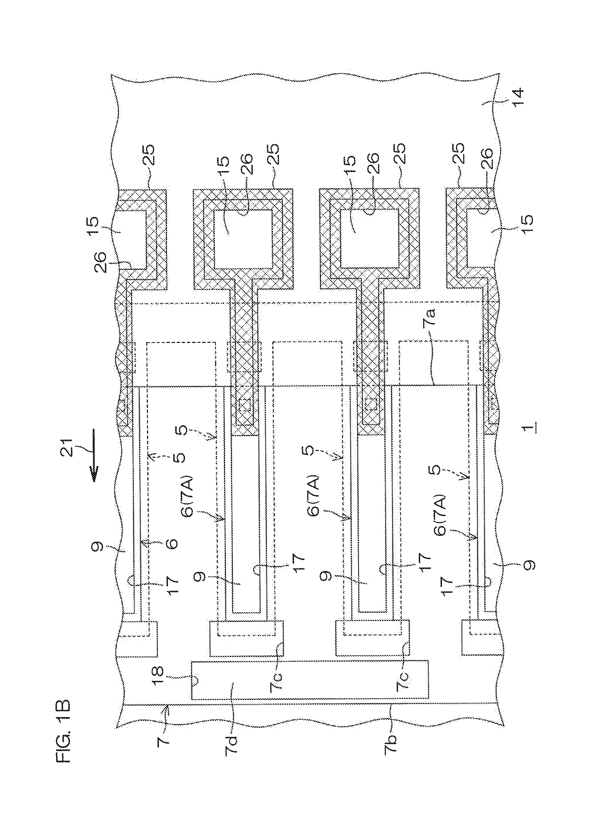
[0122]FIG. 1A is a schematic plan view of an inkjet printing head to which a first invention is applied. FIG. 1B is a schematic plan view for illustrating a region in which a passivation film is formed. FIG. 1B is a schematic plan view for illustrating a region of the interlayer insulating film in which the passivation film is not formed on a front surface. FIG. 2 is a schematic enlarged sectional view taken along line II-II in FIG. 1. FIG. 3 is a schematic enlarged sectional view taken along line III-III in FIG. 1. FIG. 4 is a schematic perspective view of the inkjet printing head. In FIG. 1A and FIG. 4, a hydrogen barrier film indicated by symbol 13 and an insulating film indicated by symbol 14 in FIG. 2 and FIG. 3 are omitted. FIG. 5 is a plan view of a planar shape of a lower electrode formed above a movable film...


PUM


Abstract

An inkjet printing head 1 includes a piezoelectric element 6 having a lower electrode 7, a piezoelectric film 8 formed above the lower electrode 7, and an upper electrode 9 formed above the piezoelectric film 8, a hydrogen barrier film 13 covering an entirety of a side surface of the upper electrode 9 and the piezoelectric film 8, and an interlayer insulating film 14 that has an opening 17 at an upper surface center of the upper electrode 9, is laminated on the hydrogen barrier film 13, and faces the entirety of the side surface of the upper electrode 9 and the piezoelectric film 8 across the hydrogen barrier film 13.

Description

BACKGROUND OF THE INVENTION[0001]1. Field of the Invention[0002]The present invention relates to a device using a piezoelectric element that uses a piezoelectric element and a method for manufacturing the same.[0003]2. Description of the Related Art[0004]An inkjet printing head is known as a device using a piezoelectric element that uses a piezoelectric element. An example of such an inkjet printing head is disclosed in Japanese Patent Application Publication No. 2013-119182. The inkjet printing head of Japanese Patent Application Publication No. 2013-119182 includes a silicon substrate having a pressure chamber, a movable film (vibrating film) supported by the silicon substrate so as to face the pressure chamber, and a piezoelectric element bonded to the movable film. The piezoelectric element is arranged by laminating a lower electrode, a piezoelectric film, and an upper electrode in that order from the movable film side. An upper surface and a side surface of the piezoelectric el...

Claims


Application Information

Patent Timeline
IPC IPC(8): H01L41/053B41J2/14B41J2/16H01L41/047H01L41/08H01L41/29
CPCH01L41/0533H01L41/0805H01L41/0475B41J2002/14241B41J2/161B41J2/14233H01L41/29B41J2/1628B41J2/1629B41J2/1631B41J2/1642B41J2/1646B41J2002/14491H10N15/10H10N30/878H10N30/877H10N30/883H10N30/875H10N30/2047H10N30/06H10N30/082H10N30/708H10N30/704
Inventor FUJIMORI, YOSHIKAZUDATE, TOMOHIRO
Owner ROHM CO LTD
Why Eureka
Try Eureka