Backpack
a backpack and backpack technology, applied in the field of backpacks, can solve the problems of not having a backpack capable of meeting our requirements, and achieve the effects of convenient and simple, reducing oxygen consumption, and preserving more energy
- Summary
- Abstract
- Description
- Claims
- Application Information
AI Technical Summary
Benefits of technology
Problems solved by technology
Method used
Image
Examples
first embodiment
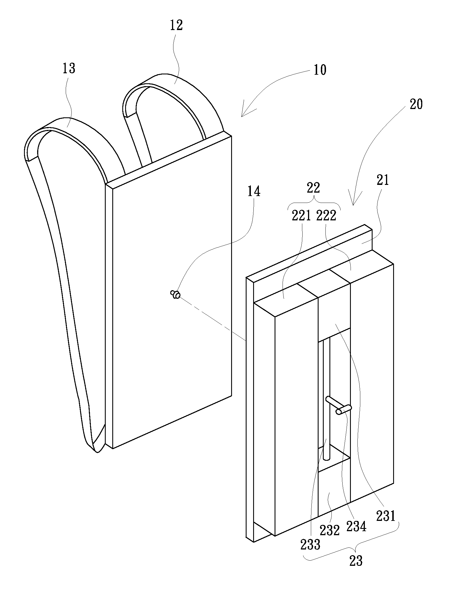
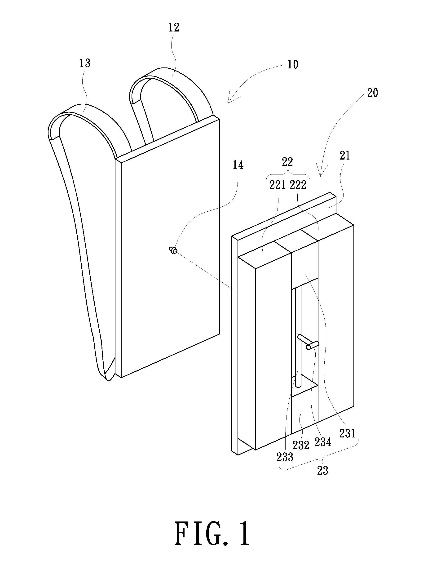
[0015]FIG. 1 is a schematic, three-dimensional view of a backpack according to the present invention. Referring to FIG. 1, the backpack includes a strapping member 10 and a base structure 20.
[0016]The strapping member 10 has a first surface and a second surface opposite to the first surface. At least two straps 12, 13 are disposed on the first surface of the strapping member 10, and at least one pivotal structure 14 is disposed on the second surface of the strapping member 10. In this illustrated first embodiment, the pivotal structure 14 is a column perpendicularly extending from the second surface of the strapping member 10. The column of the pivotal structure 14 has a flange at a free end thereof for engaging in a slot defined in the base structure 20. The pivotal structure 14 may also includes a shaft with outer threads formed at a free end thereof and a nut with inner threads formed therein.
[0017]The base structure 20 includes a plate member 21, at least one storing structure 2...
second embodiment
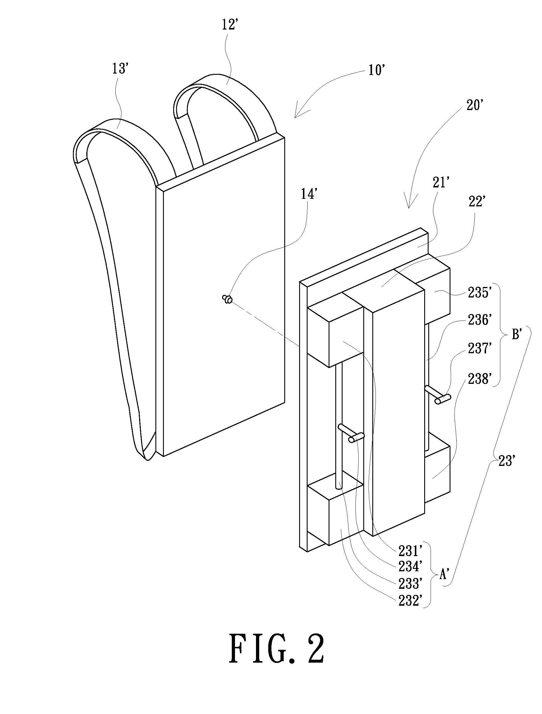
[0019]FIG. 2 is a schematic, three-dimensional view of a backpack according to the present invention. Referring to FIG. 2, the backpack includes a strapping member 10′ and a base structure 20′.
[0020]The strapping member 10′ has a first surface and a second surface opposite to the first surface. At least two straps 12′, 13′ are disposed on the first surface of the strapping member 10′, and at least one pivotal structure 14′ is disposed on the second surface of the strapping member 10′.
[0021]The base structure 20′ includes a plate member 21′, at least one storing structure 22′, and at least one containing structure 23′. The plate member 21′ is pivoted to the strapping member 10′ via the pivotal structure 14′. The plate member 21′ has a first surface and a second surface opposite to the first surface. The first surface of the plate member 21′ confronts the second surface of the strapping member 10′. The storing structure 22′ and the containing structure 23′ are disposed on the second s...
third embodiment
[0023]FIG. 3 is a schematic, three-dimensional view of a backpack according to the present invention. Referring to FIG. 3, the backpack includes a strapping member 10″ and a base structure 20″.
[0024]The strapping member 10″ has a first surface and a second surface opposite to the first surface. At least two straps 12″, 13″ are disposed on the first surface of the strapping member 10″, and at least one pivotal structure 14″ and a containing structure 23″ are disposed on the second surface of the strapping member 10″. The containing structure 23″ includes a first containing structure A″ and a second containing structure B″. The first containing structure A″ and the second containing structure B″ are vertically disposed at opposite sides of the second surface of the strapping member 10″. The first containing structure A″ includes a first upper container 231″ and a first lower container 232″. The first upper container 231″ is disposed at an upper portion of the second surface of the str...
PUM
 Abstract
Description
Claims
Application Information
 - R&D
- Intellectual Property
- Life Sciences
- Materials
- Tech Scout
- Unparalleled Data Quality
- Higher Quality Content
- 60% Fewer Hallucinations
Browse by: Latest US Patents, China's latest patents, Technical Efficacy Thesaurus, Application Domain, Technology Topic, Popular Technical Reports.
© 2025 PatSnap. All rights reserved.Legal|Privacy policy|Modern Slavery Act Transparency Statement|Sitemap|About US| Contact US: help@patsnap.com


