Real-Time Data Acquisition and Interpretation for Coiled Tubing Fluid Injection Operations

a data acquisition and data interpretation technology, applied in the field of real-time data acquisition and interpretation of data for coiled tubing fluid injection operations, can solve the problems of affecting the acid volume and flow rate required for an optimal treatment, affecting the effect of the operation, and not being able to actually achieve real-time techniques

Active Publication Date: 2016-02-18
BAKER HUGHES INC
View PDF3 Cites 36 Cited by
  • Summary
  • Abstract
  • Description
  • Claims
  • Application Information

AI Technical Summary

Benefits of technology

[0012]The present invention relates to systems and methods for acquiring data in real time during operations wherein a work fluid is injected into portions of a wellbore and interpreting acquired data during or after the downhole operation in order to optimize injection. Exemplary operations of matrix acidizing and hydraulic fracturing are described. Methods in accordance with the present invention preferably use single point sensors to acquire temperature and pressure data without requiring the sensors to remain in a stationary position. In accordance with described methods, fluid flow rates are determined using detected pressure and temperature data. Mass, momentum and energy equations are used to determine the flow rates. In addition, the methods of the present invention allow calculation of reaction heat produced by injection of the work fluid. In particular, embodiments, the wellbore is divided into discrete zones and the equations are solved for each zone. Calculated temperatures are compared to measured temperatures. Calculated results for coefficients of friction closely approximate actual measured values.

Problems solved by technology

Temperature will accelerate or decelerate the chemical reactions and, thus, impact the acid volumes and flow rates required for an optimal treatment.
Although this method is marketed as being “real time” in the industry, it has two major disadvantages which hinder its effectiveness.
Second, this is not actually a real time technique, since long periods of time, usually hours, are reported for acquiring time-dependent temperature traces.
But the arrangement is typically very costly to maintain and prone to failure.
Additionally, it cannot be used in an open hole well that has not been completed.
At present, there is no reliable method for determining the flow rates for injected fracturing fluid at locations within the wellbore in real time.

Method used


Image

  • Real-Time Data Acquisition and Interpretation for Coiled Tubing Fluid Injection Operations
  • Real-Time Data Acquisition and Interpretation for Coiled Tubing Fluid Injection Operations
  • Real-Time Data Acquisition and Interpretation for Coiled Tubing Fluid Injection Operations

Examples


Embodiment Construction

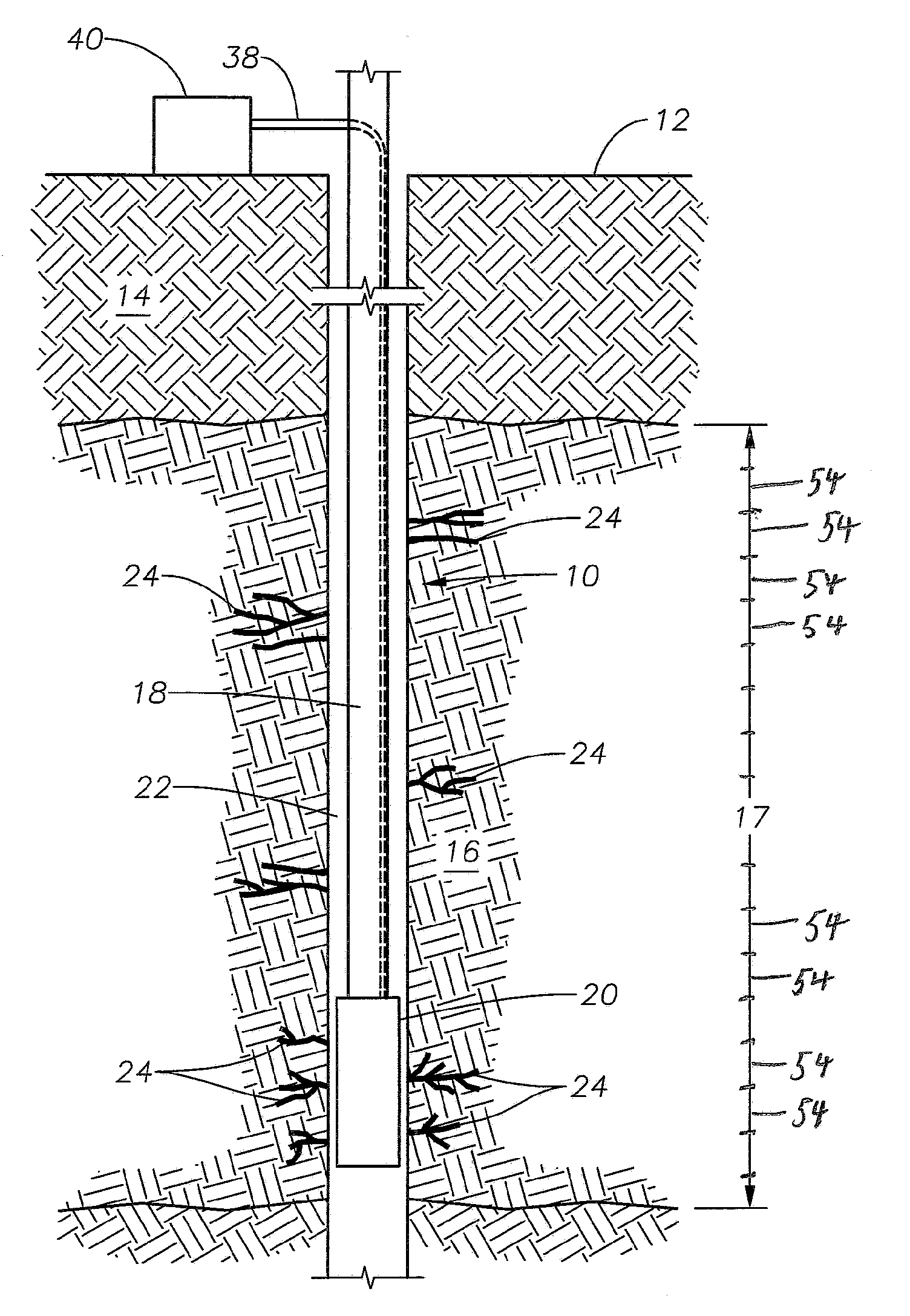
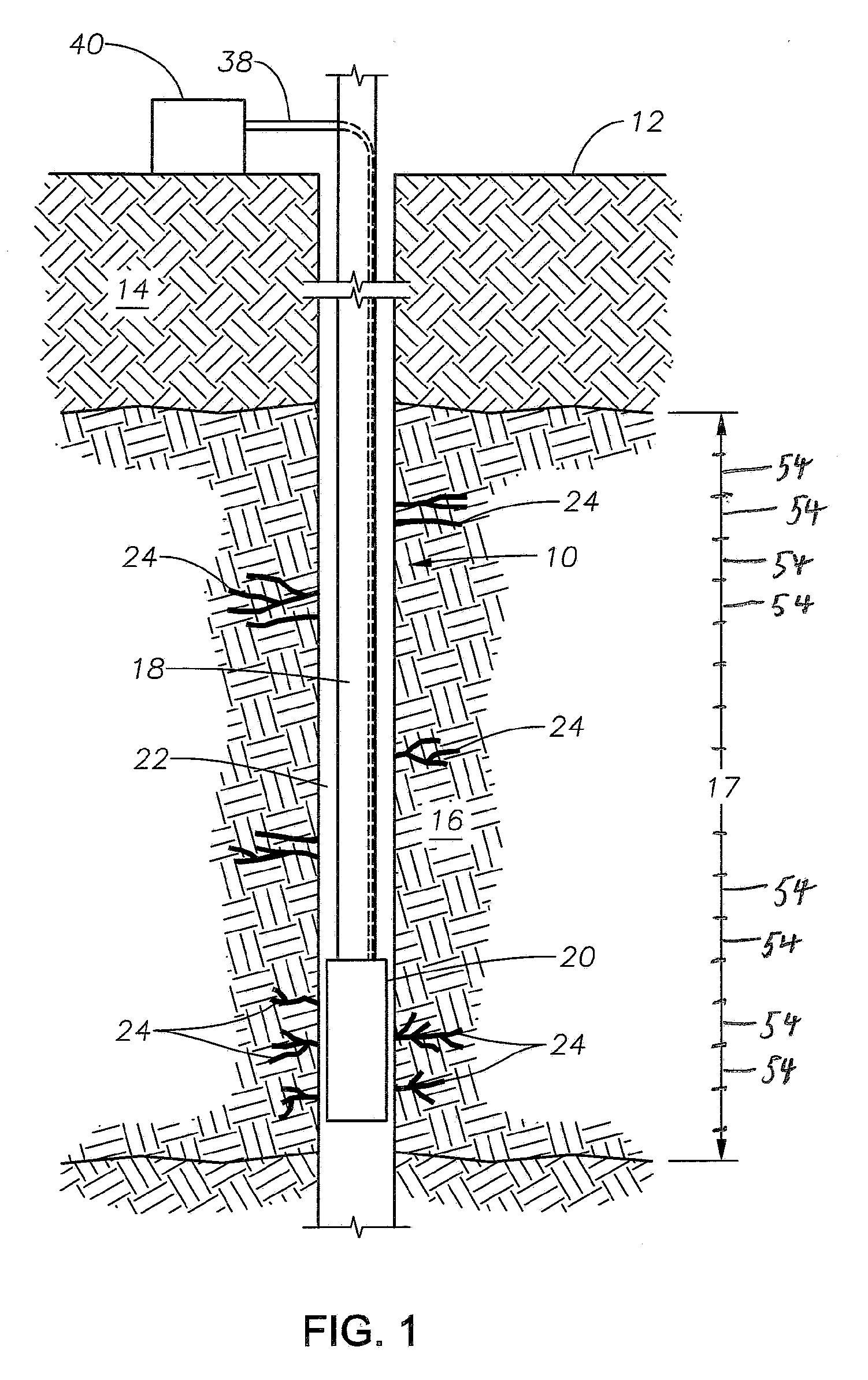
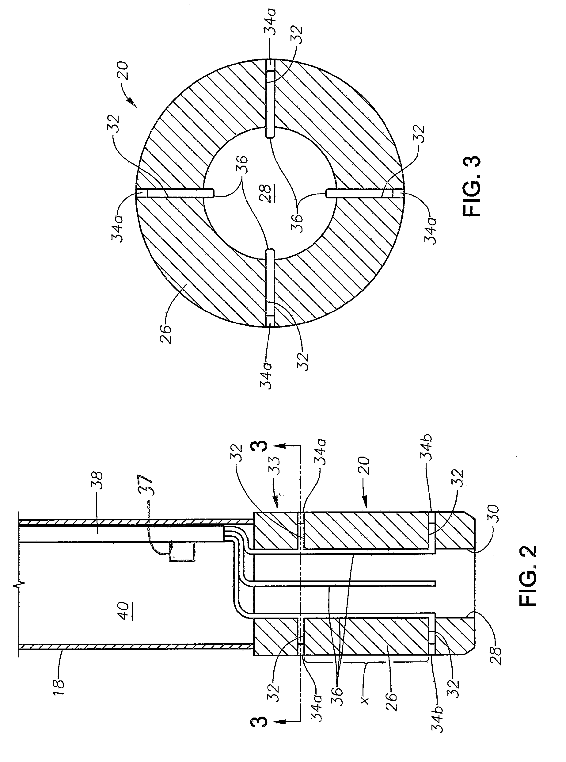
[0033]FIG. 1 illustrates an exemplary wellbore 10 which has been drilled from the surface 12 down through the earth 14 to a hydrocarbon-bearing formation 16 within which it is desired to conduct matrix acidizing. As is known, the injection of acid will cause the formation and / or lengthening and enlargement of wormholes in the surrounding formation 16, thereby increasing access to hydrocarbon fluid within the formation 16. A tool string 18 has been run into the wellbore 10 from the surface 12 and carries a bottom hole assembly 20 in the form of a matrix acidizing tool. The bottom hole assembly 20 tool is preferably a metal cylinder having temperature and pressure sensors on its outer surface and connected for signal transmission to the surface, as will be described. In a currently preferred embodiment, the tool string 18 is made up of coiled tubing, of a type known in the art, which can be injected into the wellbore 10. An annulus 22 is formed radially between the tool string 18 / bott...


PUM

PropertyMeasurementUnit
temperatureaaaaaaaaaa
sizeaaaaaaaaaa
sizeaaaaaaaaaa

Abstract

Methods for acquiring and interpreting operating parameter data during an operation to inject a work fluid into a wellbore.

Description

BACKGROUND OF THE INVENTION[0001]1. Field of the Invention[0002]The invention relates generally to data acquisition and interpretation of data for subterranean acidizing operations. In other aspects, the invention relates to data acquisition and interpretation for subterranean fracturing operations.[0003]2. Description of the Related Art[0004]Matrix acidizing is a stimulation process wherein acid is injected into a wellbore to penetrate rock pores. Matrix acidizing is a method applied for removing formation damage from pore plugging caused by mineral deposition. The acids, usually inorganic acids, such as fluoridic (HF) and or cloridic (HCl) acids, are pumped into the formation at or below the formation fracturing pressure in order to dissolve the mineral particles by chemical reactions. The acid creates high-permeability, high productivity flow channels called wormholes and bypasses the near-wellbore damage. The operation time depends on such parameters as the length of the wellbor...

Claims


Application Information

Patent Timeline
Patent Type & Authority Applications(United States)
IPC IPC(8): E21B47/10C09K8/72C09K8/80E21B43/16E21B43/26E21B43/267E21B47/06E21B47/12
CPCE21B47/10C09K8/80C09K8/72E21B43/26E21B47/122E21B43/16E21B47/06E21B47/065E21B47/123E21B43/267E21B41/0078E21B47/07
Inventor LIVESCU, SILVIUGUPTA, D. V. SATYANARAYANA
Owner BAKER HUGHES INC
Why Eureka
Try Eureka