
Physical quantity sensor, physical quantity sensor device, electronic equipment, and moving body

Active Publication Date: 2016-02-18
SEIKO EPSON CORP
View PDF2 Cites 27 Cited by
  • Summary
  • Abstract
  • Description
  • Claims
  • Application Information

AI Technical Summary

Benefits of technology

The patent text describes a way to prevent the glue from sticking and reduce the difference in capacities between components. This can make it easier to insulate the sensor's movable section from the substrate, simplify the sensor structure, and more effectively prevent sticking while reducing capacity offset.

Problems solved by technology

In the physical quantity sensor described in JP-A-2007-298405, when anodically bonding a structural body (a Si structural body) provided with a movable electrode to a glass substrate, if a glass exposed surface facing the structural body is large, an electrostatic force which is generated increases, and therefore, there is a problem in that sticking of the structural body to the glass substrate occurs.
However, a difference in capacitance (a capacity offset) between each fixed electrode and the movable electrode occurs, and according to the variation thereof, yield is deteriorated beyond an adjustment range of an integrated circuit (IC).
Further, there is a problem in that a capacity offset affects the entire sensor (refer to, for example, JP-A-2002-202320).

Method used


Image

  • Physical quantity sensor, physical quantity sensor device, electronic equipment, and moving body
  • Physical quantity sensor, physical quantity sensor device, electronic equipment, and moving body
  • Physical quantity sensor, physical quantity sensor device, electronic equipment, and moving body

Examples


modified example 1

of Physical Quantity Sensor

[0184]Next, a physical quantity sensor according to a modified example of the physical quantity sensor 200 will be described with reference to the drawing. FIG. 14 is a plan view showing a physical quantity sensor 400 according to the modified example. In addition, for convenience, in FIG. 14, illustration is made to see through the lid body 580. Further, in FIG. 14, as three axes orthogonal to each other, the X-axis, the Y-axis, and the Z-axis are shown.

[0185]Hereinafter, in the physical quantity sensor 400 according to the modified example, members having the same function as the constituent members of the physical quantity sensor 200 of FIG. 6 are denoted by the same reference numerals and a detailed description thereof is omitted.

[0186]In the physical quantity sensor 200, as shown in FIG. 6, the planar shape of the support section 540 is an H-shape (a substantially H-shape). In contrast, in the physical quantity sensor 400, as shown in FIG. 14, the pla...

modified example 2

of Physical Quantity Sensor

[0189]Next, a physical quantity sensor according to Modified Example 2 of the above-described physical quantity sensor will be described with reference to the drawing. FIG. 15 is a plan view showing a physical quantity sensor 600 according to Modified Example 2. In addition, for convenience, in FIG. 15, illustration is made to see through the lid body 580. Further, in FIG. 15, as three axes orthogonal to each other, the X-axis, the Y-axis, and the Z-axis are shown.

[0190]Hereinafter, in the physical quantity sensor 600 according to the modified example, members having the same function as the constituent members of the physical quantity sensor 300 of FIG. 13 are denoted by the same reference numerals and a detailed description thereof is omitted.

[0191]In the physical quantity sensor 300, as shown in FIG. 13, the second dummy electrode 554 has a shape in which the second dummy electrode 554 wraps around the sides of both end portions in the width direction o...

modified example 3

of Physical Quantity Sensor

[0193]Next, a physical quantity sensor according to Modified Example 3 of the above-described physical quantity sensor will be described with reference to the drawing. FIG. 16 is a plan view showing a physical quantity sensor 700 according to Modified Example 3. In addition, for convenience, in FIG. 16, illustration is made to see through the lid body 580. Further, in FIG. 16, as three axes orthogonal to each other, the X-axis, the Y-axis, and the Z-axis are shown.

[0194]Hereinafter, in the physical quantity sensor 700 according to the modified example, members having the same function as the constituent members of the physical quantity sensor 300 of FIG. 13 are denoted by the same reference numerals and a detailed description thereof is omitted.

[0195]In the physical quantity sensor 300, as shown in FIG. 13, the second dummy electrode 554 has a shape in which the second dummy electrode 554 wraps around the sides of both end portions in the width direction o...


PUM


Abstract

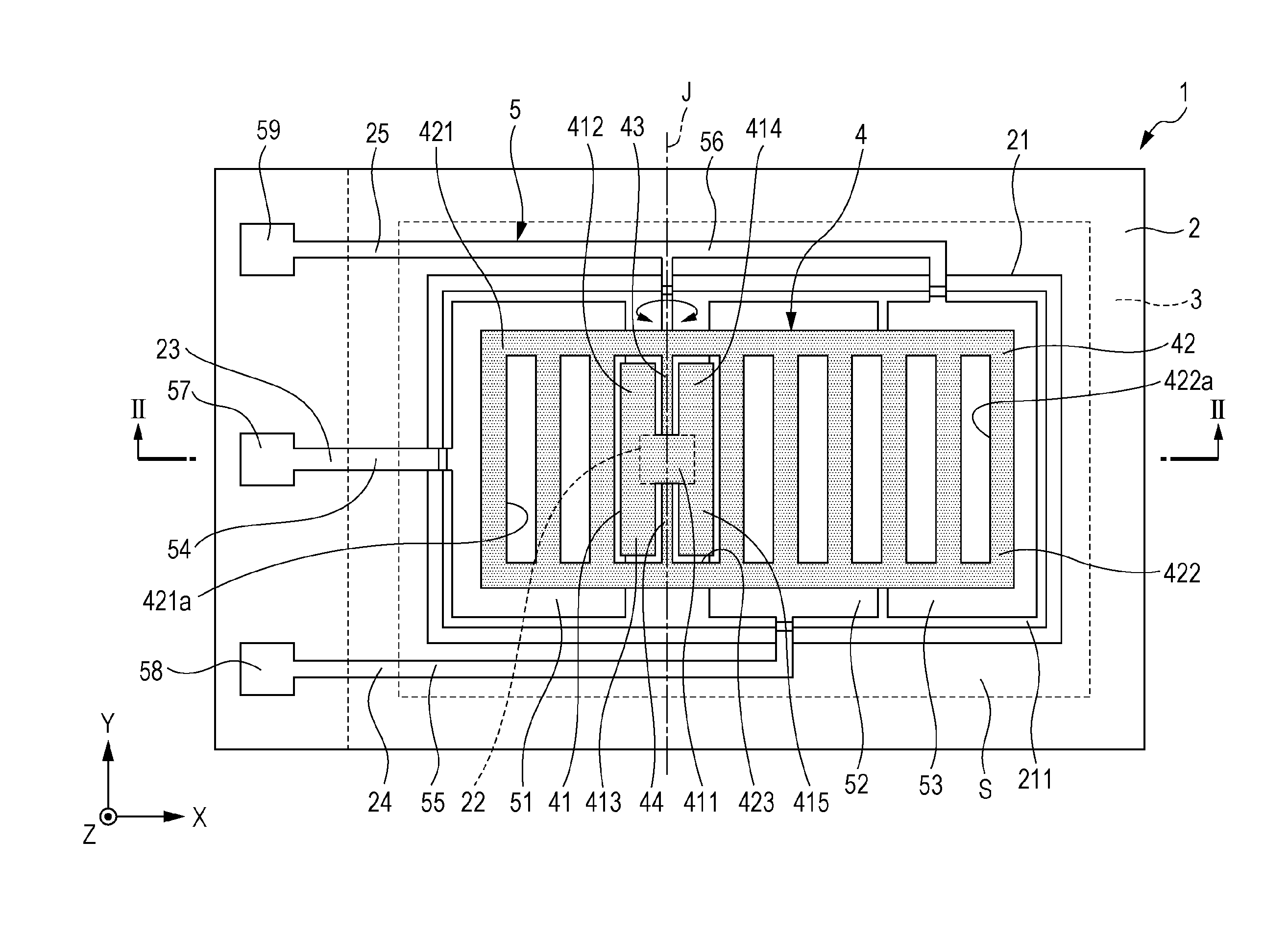
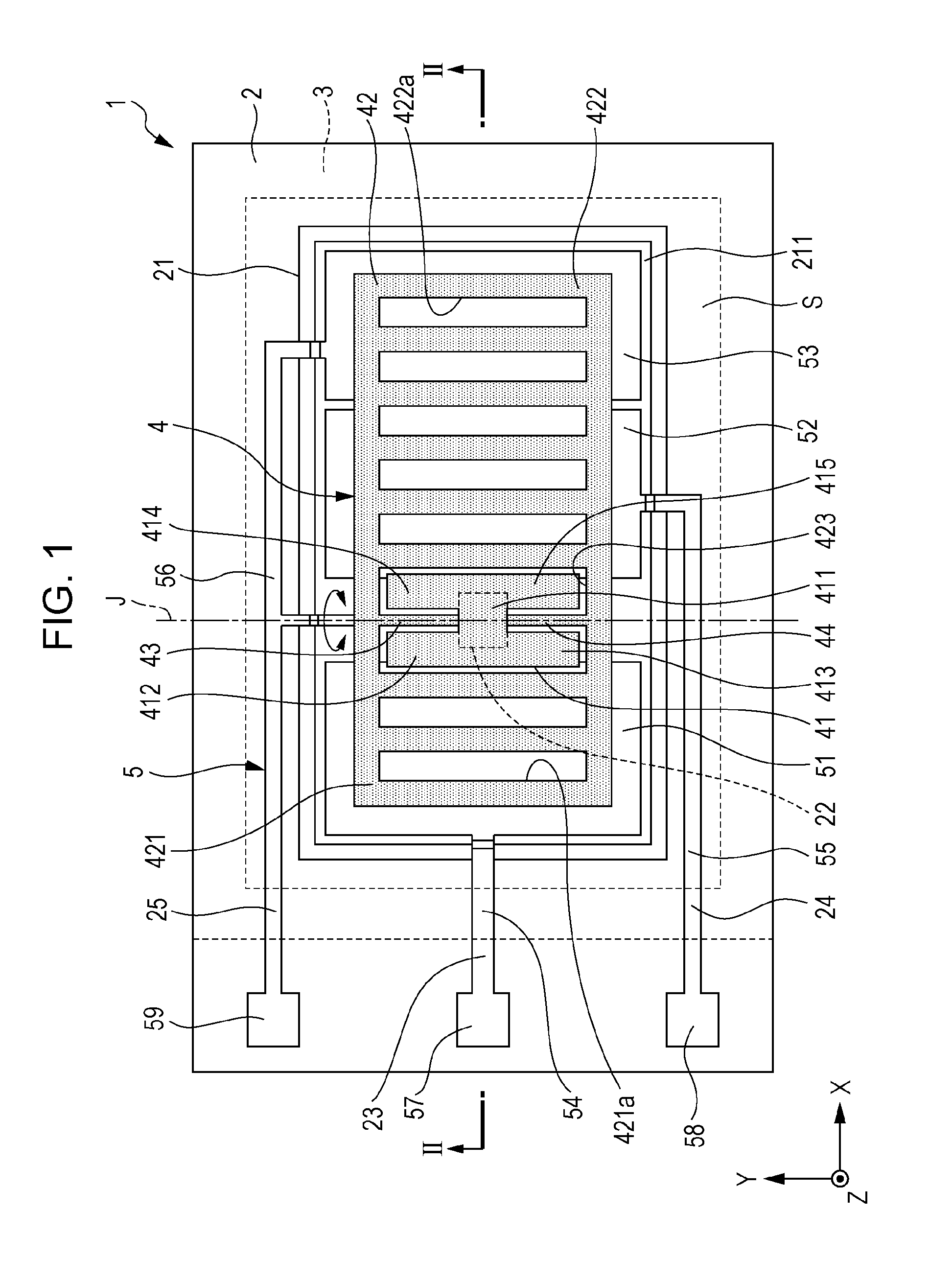
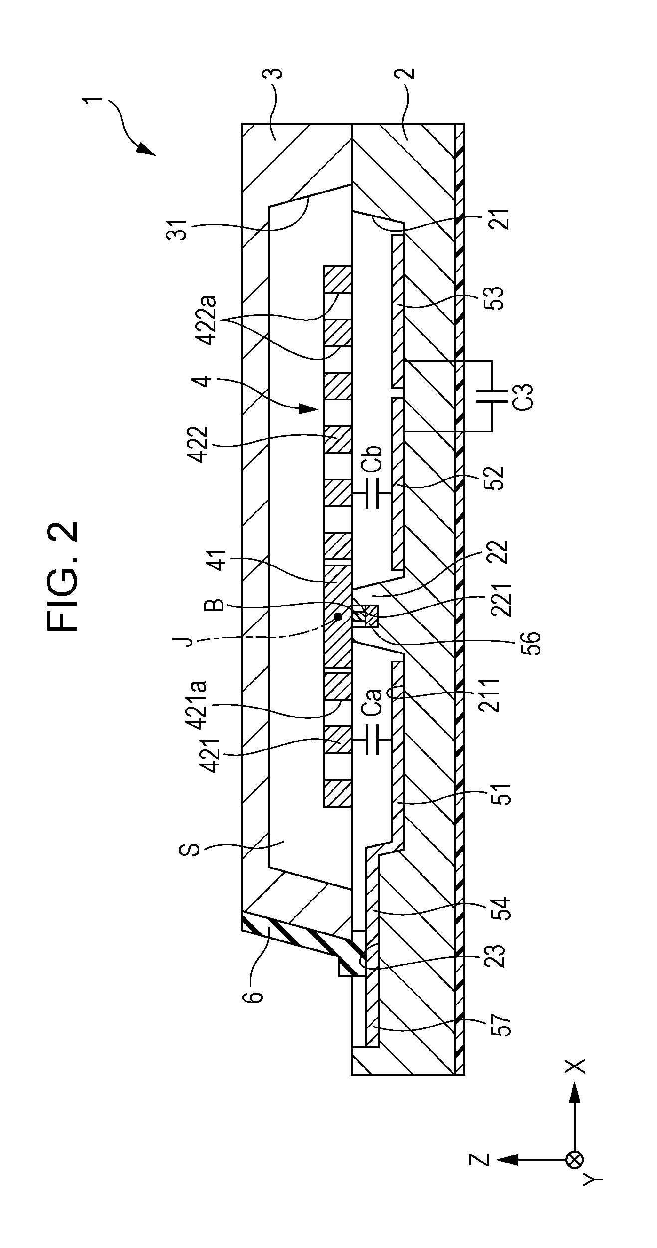
A physical quantity sensor includes: an oscillating body having a support section and a movable section which is connected to the support section through connection portions, in which the movable section has a first movable portion and a second movable portion; a first fixed electrode which is disposed to face the first movable portion; a second fixed electrode which is disposed to face the second movable portion; and a dummy electrode which is disposed to face the second movable portion so as not to overlap the second fixed electrode and has the same potential as potential of the oscillating body, in which the first fixed electrode is disposed such that a portion thereof overlaps the support section when viewed in a plan view.

Description

BACKGROUND[0001]1. Technical Field[0002]The present invention relates to a physical quantity sensor, a physical quantity sensor device, electronic equipment, and a moving body.[0003]2. Related Art[0004]In recent years, a physical quantity sensor for detecting a physical quantity such as acceleration by using, for example, a silicon micro electro mechanical systems (MEMS) technique has been developed.[0005]As the physical quantity sensor, a physical quantity sensor having a movable electrode which has a large plate portion and a small plate portion and is supported on an insulating layer such that the plate portions can oscillate in a seesaw manner, a fixed electrode which is provided on the insulating layer to face the large plate portion, and a fixed electrode which is provided on the insulating layer to face the small plate portion is known (refer to, for example, JP-A-2007-298405).[0006]In the physical quantity sensor described in JP-A-2007-298405, when anodically bonding a struc...

Claims


Application Information

Patent Timeline
IPC IPC(8): G01P15/125
CPCG01P15/125G01C19/5755G01C19/5769G01P2015/0831
Inventor TANAKA, SATORU
Owner SEIKO EPSON CORP
Learn More