Optical Field Transformation Methods and Systems

a technology of optical field and transformation method, applied in the field of optical field transformation method and system, can solve the problems of limiting the resolution of optical system, often required non-imaging optical system,

Active Publication Date: 2016-02-18
SOSKIND YAKOV +2
View PDF3 Cites 3 Cited by
  • Summary
  • Abstract
  • Description
  • Claims
  • Application Information

AI Technical Summary

Benefits of technology

[0019]In accordance with one aspect of the invention, optical field transformation techniques are provided that can alter the shape and size of PSFs produced by optical systems, as well as the shape and size of the far field distributions produced by laser beams and their combinations.

Problems solved by technology

On the other hand, non-imaging optical systems are often required to produce various output light patterns by transforming the propagating radiation.
Optical systems well corrected for aberrations are termed as “diffraction-limited.” Diffraction effects limit the resolution of optical systems and prevent propagating radiation from being focused into infinitely small spots with infinitely high power densities.

Method used


Image

  • Optical Field Transformation Methods and Systems
  • Optical Field Transformation Methods and Systems
  • Optical Field Transformation Methods and Systems

Examples


first embodiment

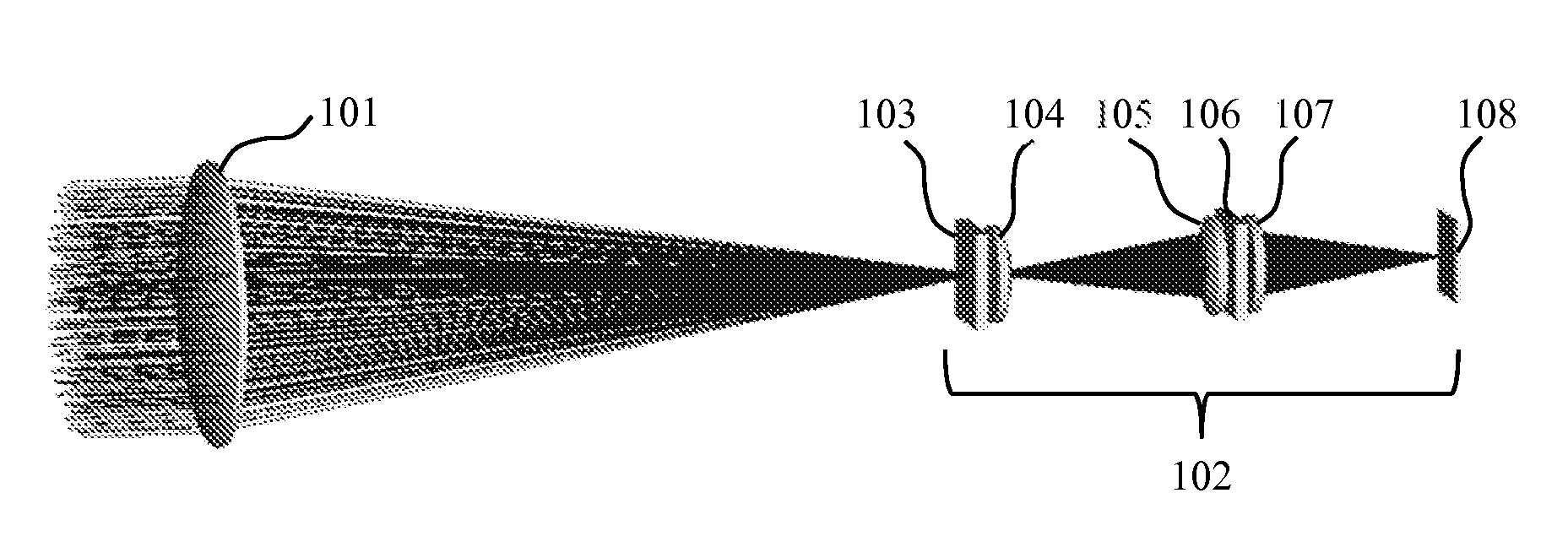
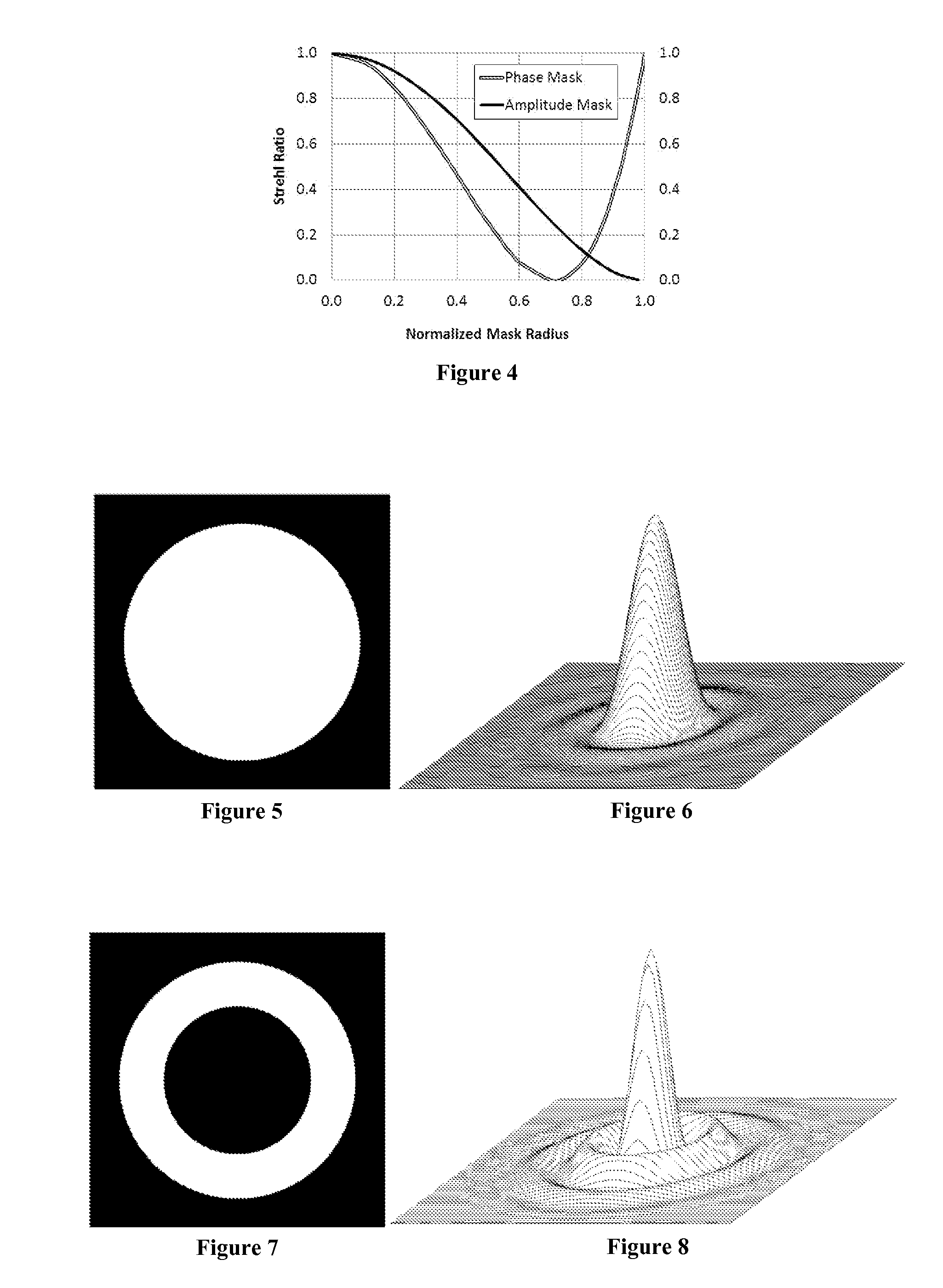
[0146]The first embodiment of the present invention is designed to transform PSF distributions of diffraction-limited optical systems with uniformly illuminated circular apertures, also known as Airy distributions. FIG. 24 shows the optical layout corresponding to the first embodiment of the present invention. It shows a diffraction-limited optical system 101 producing an Airy distribution in its back focal plane, as well as an optical system 102 for transforming the Airy distribution. The input intensity distribution and the Airy intensity distribution in the focal plane of a diffraction-limited optical system were shown earlier in FIGS. 5 and 6, respectively.

[0147]The optical system 102 in accordance with the first embodiment of the present invention transforms the PSF distribution of the diffraction-limited optical system 101 and produces the transformed optical field in the output plane 108. The optical system 102 contains a diffractive structure 103 placed within the focused op...

second embodiment

[0162]The second embodiment of the present invention is designed to transform PSF distributions of optical systems with central obscurations. This type of optical system is commonly found in reflective astronomical telescopes. The optical layout of the second embodiment of the present invention is presented in FIG. 40. It shows the optical system 200 with central obscuration producing a PSF distribution in the back focal plane, as well as the optical system 203 for transforming the PSF of the optical system 200 and producing the transformed optical field distribution in the output plane 206. The optical system 200 consists of a primary mirror 201 with a central opening and a secondary mirror 202 obstructing the aperture of the primary mirror 201. The uniformly illuminated aperture and the PSF intensity distribution of an optical system with central obscuration were shown in FIGS. 7 and 8, respectively.

[0163]In accordance with the second embodiment, the primary mirror 201 of the opti...

third embodiment

[0179]The third embodiment of the present invention is designed to transform optical field distributions produced by optical systems containing multiple spatially distributed apertures. The optical layout of the third embodiment is presented schematically in FIG. 62. The optical layout contains an optical system 300 composed of a segmented primary mirror and a secondary mirror 307. The primary mirror of the optical system 300 is comprised of six off-axis segments 301 through 306. Radiation collected by the segments 301 through 306 is reflected onto the secondary mirror 307 and is then redirected by the secondary mirror onto an image plane, where the PSF is produced. The image plane location depends on the location of an object or light source with respect to the optical system 300. For the purpose of the following discussion, we assume that objects are located at infinity, and therefore the image plane is located in the back focal plane of the optical system 300.

[0180]The optical la...


PUM


Abstract

A method of performing coherent transformations of optical fields includes forming a far field distribution of the input optical field. A fraction of the formed far field is diffracted by producing localized discontinuities within said far field. A Fraunhofer diffraction pattern of the diffracted optical field is formed. The Fraunhofer diffraction pattern is modified by producing localized optical path differences within the Fraunhofer diffraction pattern. The transformed output optical field is produced in the far field with respect to the modified Fraunhofer diffraction pattern.

Description

I. FIELD OF THE INVENTION[0001]The present invention relates to methods and systems employed for modification of optical fields. More specifically, it relates to methods and systems for transforming the shape and size of optical field distributions produced by optical systems.II. BACKGROUND OF THE INVENTION[0002]One of the most fundamental characteristics of imaging optical systems is the ability to produce sharp images of objects and to resolve fine details within these objects. On the other hand, non-imaging optical systems are often required to produce various output light patterns by transforming the propagating radiation. In several photonics applications, for example, it is required to produce high peak irradiance or radiance optical fields with complex, spatially structured radiation patterns.[0003]An optical system's response to a point source, known as the point-spread function (PSF) of the optical system, represents one of the most fundamental characteristics of the optica...

Claims


Application Information

Patent Timeline
Patent Type & Authority Applications(United States)
IPC IPC(8): G02B27/42G02B27/00G02B27/09
CPCG02B27/4266G02B27/0037G02B27/0087G02B27/0944G02B27/0927
Inventor SOSKIND, YAKOVSOSKIND, MICHAELSOSKIND, ROSE
Owner SOSKIND YAKOV
Why Eureka
Try Eureka