Method and structure for plasmonic optical trapping of nano-scale particles

Active Publication Date: 2016-02-18
THE BOARD OF TRUSTEES OF THE LELAND STANFORD JUNIOR UNIV
View PDF0 Cites 16 Cited by
  • Summary
  • Abstract
  • Description
  • Claims
  • Application Information

AI Technical Summary

Benefits of technology

[0021]Furthermore, a coaxial plasmonic aperture in accordance with the illustrative embodiment of the invention has greater transmissio

Problems solved by technology

Despite these advances, optical trapping and manipulation of individual particles with sizes smaller than the wavelength of light remains a considerable challenge.
The problem is inherent to the light beam itself.
If the specimen in question is much smaller than 200 nm, only very loose control of the specimen is possible since, relative to its size, the specimen is being trapped in a much larger potential well.
Furthermore, the optical force that light can exert on an obj

Method used


Image

  • Method and structure for plasmonic optical trapping of nano-scale particles
  • Method and structure for plasmonic optical trapping of nano-scale particles
  • Method and structure for plasmonic optical trapping of nano-scale particles

Examples


Embodiment Construction

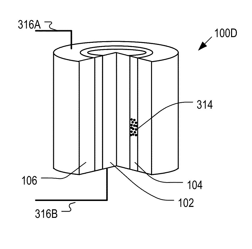
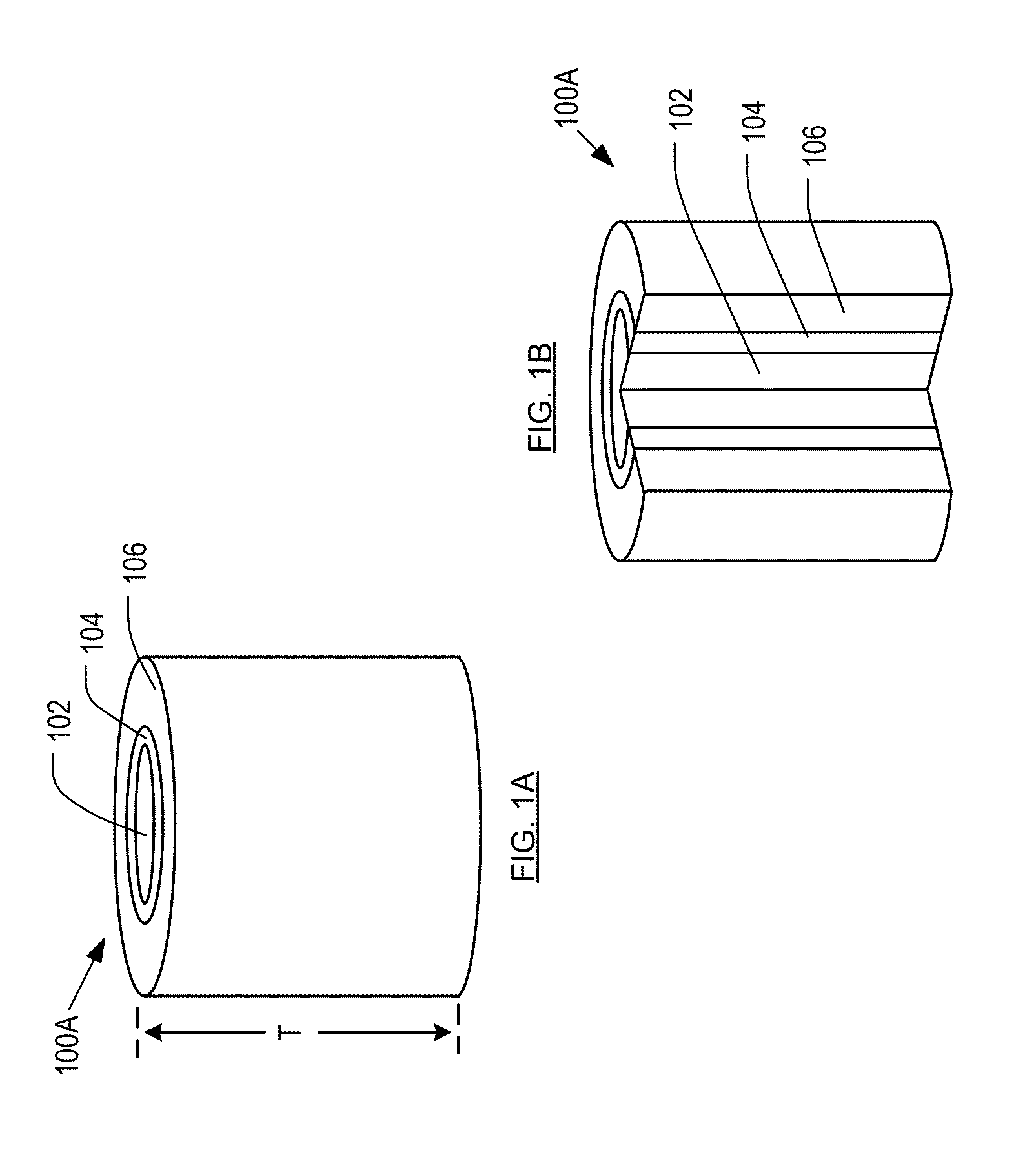
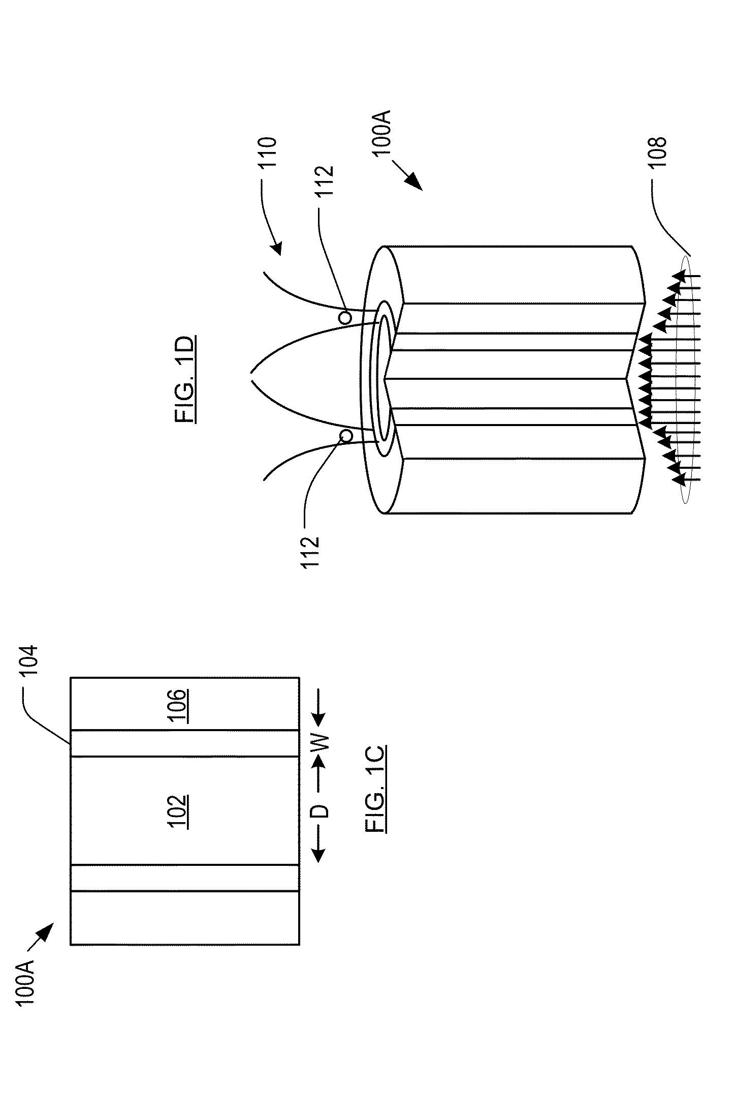
[0040]FIGS. 1A-1D depict coaxial plasmonic aperture 100A in accordance with the illustrative embodiment of the present invention. Coaxial plasmonic aperture 100A comprises core 102, channel 104, and cladding 106, inter-related as shown.

[0041]In some embodiments, core 102 has a cylindrical shape. In some alternative embodiments, core 102 has a polygonal perimeter. Core 102 preferably comprises a metal, more preferably a noble metal. In some alternative embodiments, highly-doped semiconductors or metals can be used. In the illustrative embodiment, core 102 comprises silver.

[0042]A change in the core material will result in a change in the plasmonic resonance frequency of coaxial plasmonic aperture 100A. Thus, changing the core material results in a shift in the operating range of coaxial plasmonic aperture 100A, which, as a function of trapping application, might be useful. Those skilled in the art, after reading this specification, will be able to determine the shift in operating ran...


PUM


Abstract

Methods and article for optically trapping nano-sized objects by illuminating a coaxial plasmonic aperture are disclosed.

Description

STATEMENT OF RELATED CASES[0001]This case is a continuation-in-part of U.S. patent application Ser. No. 14 / 209,904 filed Mar. 13, 2014, which claims priority to U.S. Provisional Patent Application Ser. No. 61 / 779,528 filed on Mar. 13, 2013, both of which applications are incorporated by herein by reference.STATEMENT REGARDING FEDERALLY-SPONSORED RESEARCH[0002]This invention was made with Government support under contract FA9550-11-1-0024 awarded by the Air Force Office of Scientific Research. The Government has certain rights in the invention.FIELD OF THE INVENTION[0003]The present invention relates to optical trapping of nano-sized objects.BACKGROUND OF THE INVENTION[0004]Electromagnetic beams can serve as “tweezers,” enabling small objects to be accelerated, manipulated, or trapped using light alone. Optical tweezers were first introduced in 1970, using a laser beam to trap dielectric beads in lower-refractive-index media. Upon interaction with the laser, the bead was both acceler...

Claims


Application Information

Patent Timeline
IPC IPC(8): G21K1/00
CPCG02B6/264G21K1/006G02B6/1226
Inventor DIONNE, JENNIFER ANNESALEH, AMR AHMED ESSAWI
Owner THE BOARD OF TRUSTEES OF THE LELAND STANFORD JUNIOR UNIV
Why Eureka
Try Eureka